Surface-mounted antenna and communications apparatus comprising same

a communication apparatus and antenna technology, applied in the direction of resonant antennas, battery/fuel cell control arrangements, resonant antennas, etc., can solve the problems of impedance matching, limiting the use of high-dielectric constant materials, and not necessarily satisfactory in achieving sufficient miniaturization and height reduction. achieve the effect of high gain

Inactive Publication Date: 2005-03-29
HITACHI METALS LTD
View PDF10 Cites 62 Cited by
  • Summary
  • Abstract
  • Description
  • Claims
  • Application Information

AI Technical Summary

Benefits of technology

[0013]Accordingly, an object of the present invention is to provide a surface-mounted antenna whose impedance matching can easily be achieved even when a material having a relatively high dielectric constant is used for miniaturization, which has high gain, wide band and omni-directionality, particularly suitable for GPS, wireless LAN, etc.
[0015]As a result of intense research in view of the above objects, the inventors have found that with an impedance-matching function provided by a current-feeding electrode structure having not only capacitance but also inductance, impedance matching can easily be achieved even when a material having a relatively high dielectric constant is used for the substrate, resulting in a small surface-mounted antenna with omni-directionality. The present invention is based on this finding.

Problems solved by technology

However, because conventional surface-mounted antennas have characteristics, which are deteriorated with miniaturization and reduction in height, they are not necessarily satisfactory in achieving sufficient miniaturization and reduction in height.
However, there is actually a limit in the use of high-dielectric constant materials, and only dielectric substrates having dielectric constants ∈r of up to about 4 have been put into practical use, because a higher dielectric constant ∈r than the above level causes the problem of impedance matching.
Because input impedance at a current-feeding point is likely to change largely in a surface-mounted antenna having a high dielectric constant, it has become difficult to overcome the problem of impedance matching as the miniaturization.
However, in the conventional antenna shown in FIG. 21, the current-feeding electrode and the radiation electrode are not directly connected but only capacitance-coupled, without using inductance for impedance matching.
Accordingly, if this antenna is made smaller and reduced in height, it cannot have high characteristics easy for impedance matching.
However, this antenna not only has a structure complicated, but also suffers from increase in production cost.
However, such antenna is not suitable for applications requiring omni-directionality, such as GPS, wireless LAN, etc.
In addition, because no attention is paid to miniaturization, radiation efficiency, gain and bandwidth, there are problems to be solved to use it for GPS, etc.

Method used


Image

  • Surface-mounted antenna and communications apparatus comprising same
  • Surface-mounted antenna and communications apparatus comprising same
  • Surface-mounted antenna and communications apparatus comprising same

Examples


first embodiment

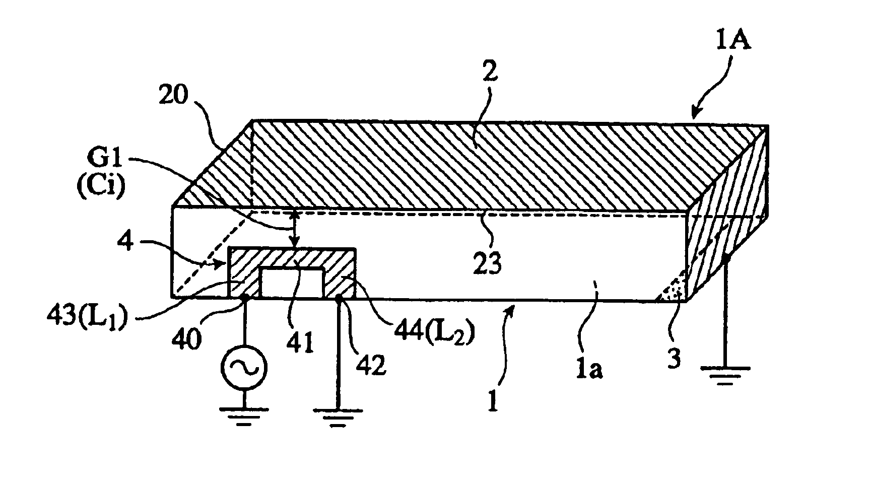
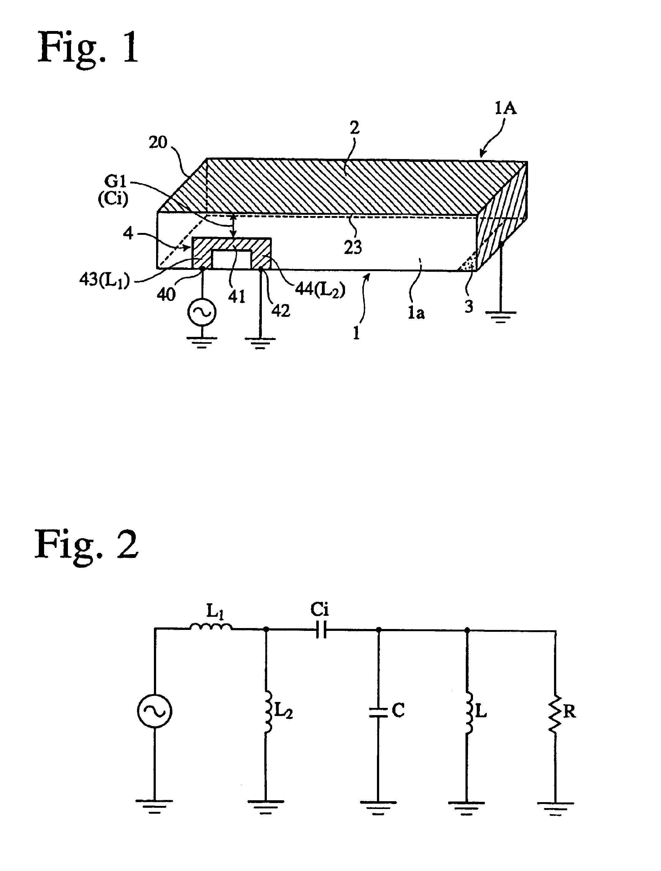
[0077]FIG. 1 is a perspective view showing a surface-mounted antenna according to the present invention. This antenna 1A comprises a radiation electrode 2 formed on an upper surface of a rectangular substrate 1, a grounding electrode 3 connected to one end of the radiation electrode 2, and a current-feeding electrode 4 formed on a side surface separate from the radiation electrode 2 with a predetermined gap G1. The other end of the radiation electrode 2 is an open tip end 20. Though the antenna 1A has a structure similar to the reverse F antenna, it is different from the reverse F antenna in that the current-feeding electrode 4 faces the radiation electrode 2 with a gap G1. There is no electrode other than soldering electrodes on a bottom surface 1a of the substrate 1, and the antenna 1A is mounted onto an area of a circuit board free from a ground conductor. Accordingly, the antenna 1A exhibits omni-directionality with a radiating electric field pattern, which is substantially unif...

second embodiment

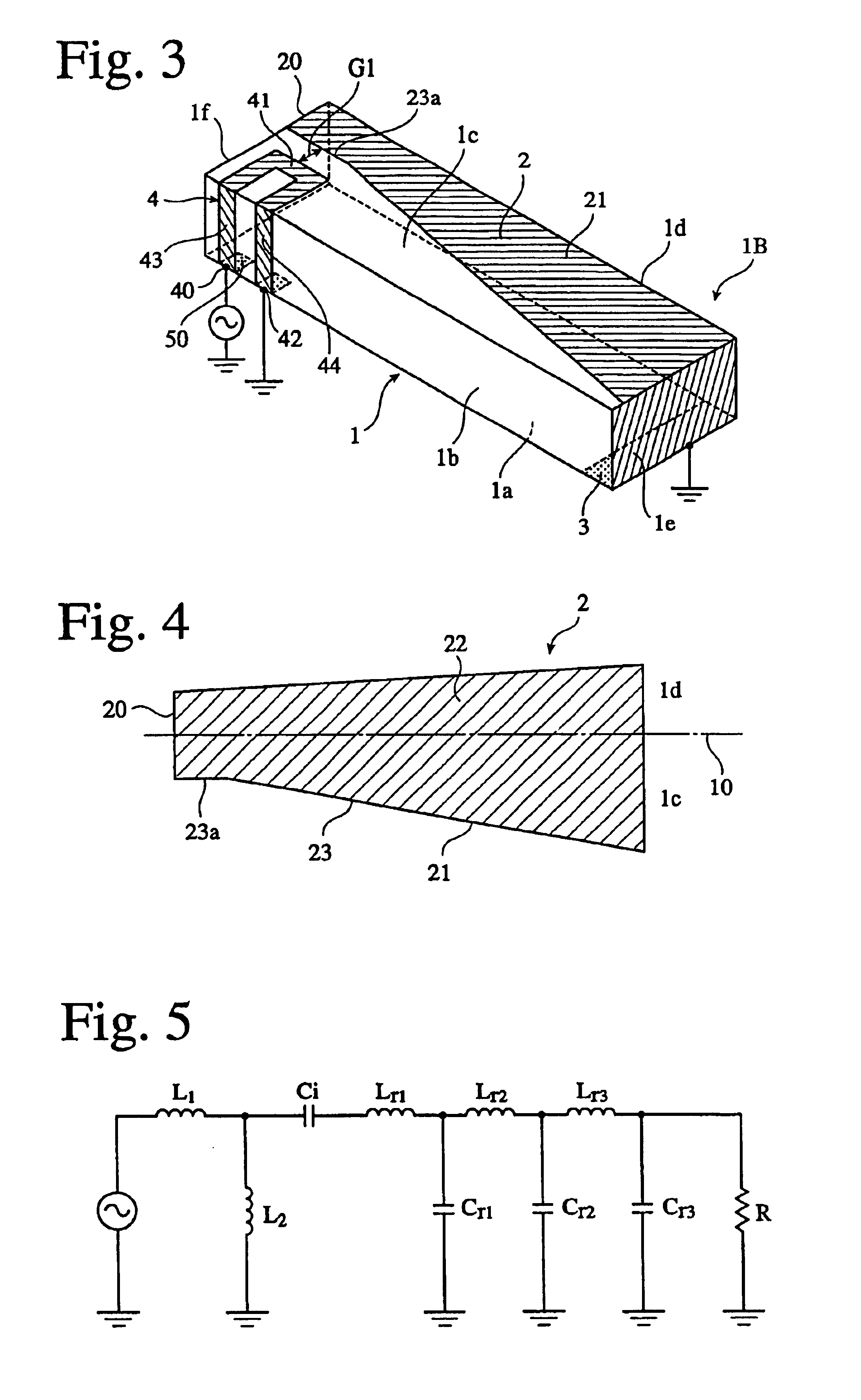
[0080]FIG. 3 is a perspective view showing a surface-mounted antenna FIG. 4 is a development of its radiation electrode, and FIG. 5 is a view showing an equivalent circuit of this antenna.

[0081]The surface-mounted antenna 1B in this embodiment is for GPS, comprising a rectangular substrate 1, a radiation electrode 2 formed on an upper surface 1c and an adjacent side surface 1d, a grounding electrode 3 connected to one end of the radiation electrode 2, and a current-feeding electrode 4 formed on the substrate 1 in a portal shape extending from a side surface 1b to an upper surface 1c in a longitudinal direction. The current-feeding electrode 4 may be formed only on the side surface 1b. The arrangement and shape of the portal current-feeding electrode 4 may be determined by taking into consideration a balance of impedance matching and increase in bandwidth.

[0082]The radiation electrode 2 in this embodiment has a shape extending from one end of the substrate 1 in a longitudinal direct...

third embodiment

[0087]FIG. 7 shows a surface-mounted antenna according to the present invention. The same symbols and reference numerals are assigned to the same portions as in the above embodiments, and thus their explanation will be omitted. As in the above embodiments, a radiation electrode 24 has substantially trapezoidal shape extending from one end of the substrate 1 to the other end in a longitudinal direction with its width narrowing substantially continuously and / or stepwise, and a current-feeding electrode 4 is formed on the substrate 1, extending from a side surface 1b to an upper surface 1c. In this embodiment, because the current-feeding electrode 4 is in a U shape, a gap between the aligned portion 41 and the radiation electrode 24 is not constant, with relatively small capacitance. Such radiation electrode 24 and current-feeding electrode 4 need not be in parallel, but they need only be partially aligned.


PUM


Abstract

A surface-mounted antenna comprising a substrate made of a high-dielectric constant material having a dielectric constant ∈r of 6 or more, a ribbon-shaped radiation electrode having one end which is grounded and the other end which is open, a grounding electrode connected or capacitance-coupled to one end of the radiation electrode, and a current-feeding electrode in a portal shape formed on a side surface separate from the radiation electrode with a gap; the current-feeding electrode having a current-feeding portion at one end, a grounding portion at the other end, and a portion substantially in alignment with the radiation electrode between them; and the length of the aligning portion, a gap width or a portal shape being able to be properly set such that capacitance owned by the current-feeding electrode and inductance can be adjusted for easily achieving impedance matching.

Description

FIELD OF THE INVENTION[0002]The present invention relates to a small antenna comprising a substrate made of dielectric or magnetic materials such as ceramics, resins, etc., particularly to a surface-mounted antenna having an impedance-matching function in its current-feeding electrode, and a communications apparatus comprising such a surface-mounted antenna.BACKGROUND OF THE INVENTION[0003]Surface-mounted antennas are used for global positioning systems (GPS), local area networks (wireless LAN), etc. with carrier waves in a GHz band. The miniaturization of mobile gears proceed at a dramatic speed, and the surface-mounted antennas are required to be small with reduced height, have good radiation efficiency without directionality, and further be operable in a wide band. However, because conventional surface-mounted antennas have characteristics, which are deteriorated with miniaturization and reduction in height, they are not necessarily satisfactory in achieving sufficient miniaturiz...

Claims


Application Information

Patent Timeline
Patent Type & Authority Patents(United States)
IPC IPC(8): H01Q1/38H01Q9/04H01Q1/24H01Q1/36H01Q9/40H01Q9/42
CPCH01Q1/243H01Q9/0421H01Q1/38Y02T10/70B62K5/027B60L50/66B60L58/12B62K2202/00B62K2204/00B60L2200/12
Inventor AOYAMA, HIROYUKIKIKUCHI, KEIKOTAKAKI, YASUNORIHAGIWARA, HIDETOSHI
Owner HITACHI METALS LTD
Why Eureka
Try Eureka