Low noise encoding and decoding method

a low noise, encoding and decoding technology, applied in the field of image compression, can solve the problems of blocky gamma correction reduces the visibility of quantization noise contained in the compressed image, and other noticeable edge artifacts in the reconstructed imag

Inactive Publication Date: 2005-03-29
THOMSON LICENSING SA
View PDF21 Cites 89 Cited by
  • Summary
  • Abstract
  • Description
  • Claims
  • Application Information

AI Technical Summary

Problems solved by technology

Gamma correction reduces the visibility of quantization noise contained in the compressed image, especially in the dark regions of the image.
However, in a real system a trade-off is made between the information to transmit and the quantization step size for an available bandwidth.
If the system does not drop sufficient coefficients for quantization, the system increases the quantization step size resulting in blocky artifacts in the reconstructed image.
If the picture loses too much high frequency information during the compression process, the reconstructed image will contain other noticeable edge artifacts.
These problems occur within the GA system as currently defined.
Compressing the HD image signal further only decreases displayed picture quality.
Satellite broadcast providers are unwilling to transmit HD signals because only one program can be transmitted at a time in a transponder.
To date, compressing an HD program sufficiently to fit two programs in one satellite channel (for example, 24 MHz 4-PSK Modulation) at the same time results in unacceptable viewer picture quality.
Therefore, satellite broadcast providers are hesitant to broadcast HDTV due to inefficient use of the channel.
Likewise, terrestrial broadcast providers are reluctant to commit to providing full HD programs when one program fully occupies a channel in which several SD programs can reside.

Method used


Image

  • Low noise encoding and decoding method
  • Low noise encoding and decoding method
  • Low noise encoding and decoding method

Examples


Embodiment Construction

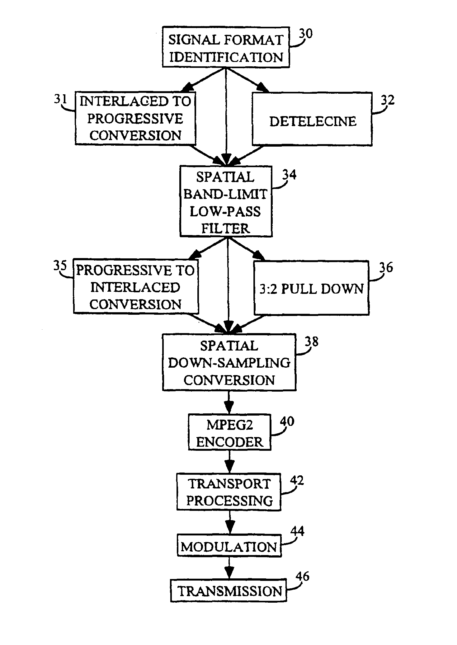
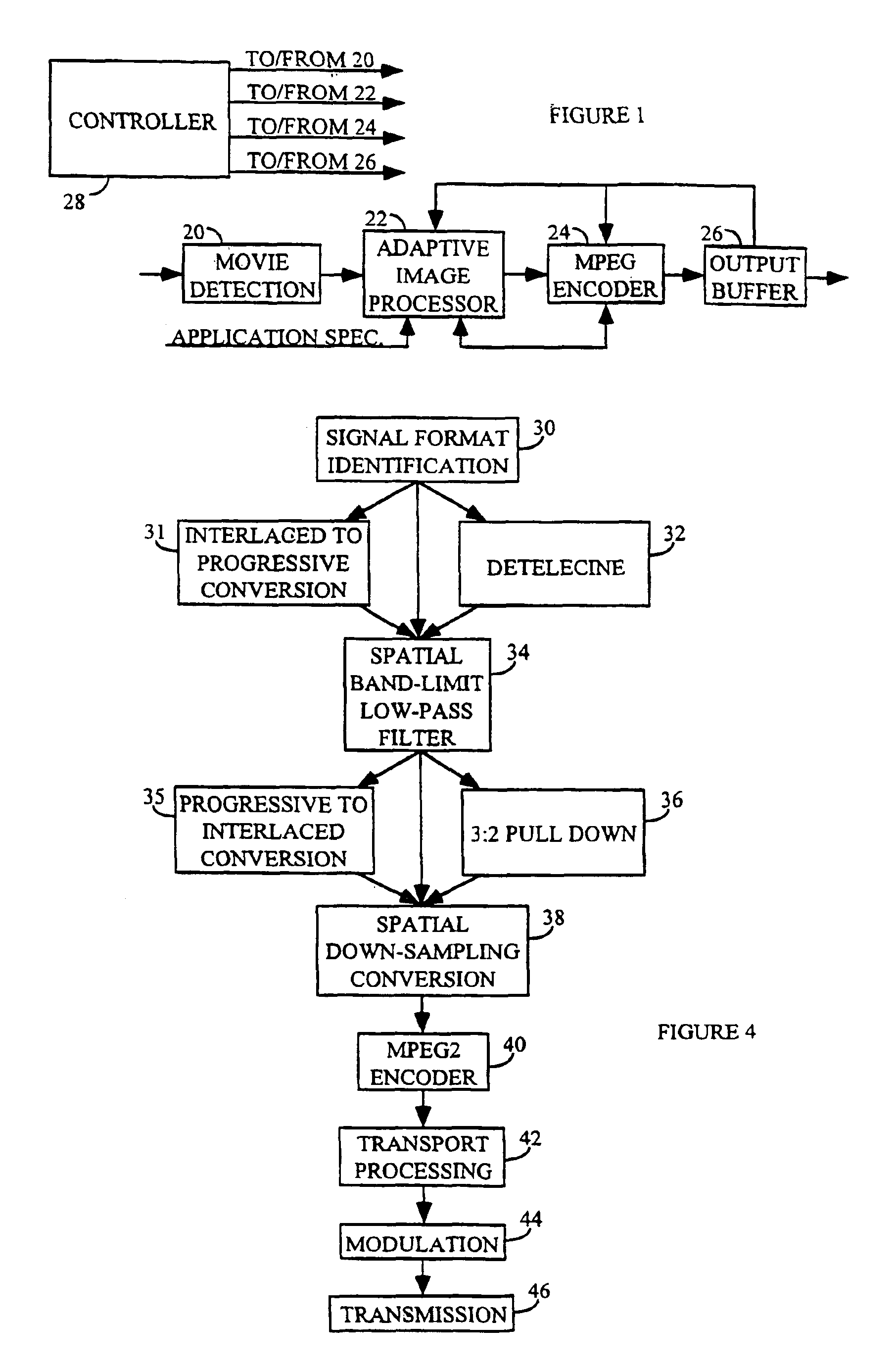
An MPEG2 encoder including apparatus according to the principles of the present invention includes a two dimensional (vertical and horizontal, for example) filter prior to the encoder. The encoder, the output buffer and the filter each produce information which may be utilized by the other units to improve overall efficiency. Such information concerns image motion, image contrast, quantization matrix selection, scale factor selection, bit rate out of each unit, image texture, for example. The information is communicated between the units by a controller which oversees the encoding process, or by individual controllers resident in each unit.

The controller evaluates the incoming information and identifies commonalties over a group of pictures, a frame, or a partial frame which can be advantageously used to modify the operation of the filter and / or the encoder to efficiently encode the group, frame or partial frame to the target bit rate. Generally, the filter is adjusted because adjus...


PUM


Abstract

An adaptive digital image processor precedes an MPEG2 encoder. The processor receives a high definition video signal intended for broadcast or storage, and adaptively low-pass filters the signal. The signal is subjected to low-pass two-dimensional filtering to eliminate encoding artifacts and related noise. The video signal is then horizontally down-sampled to create a lower resolution hybrid signal. A receiver decodes and decompresses the hybrid signal. The hybrid signal is upsampled to its original resolution using existing hardware and software with a software modification.

Description

FIELD OF THE INVENTIONThis invention concerns image compression for reducing the bandwidth requirements of a digital video encoder.BACKGROUND OF THE INVENTIONThe United States Federal Communications Commission (FCC) has approved a digital high definition television (HDTV) standard proposed by the Grand Alliance (GA), clearing the way for terrestrial digital television broadcasting in the United States. The GA HDTV system adopted the Motion Pictures Expert Group (MPEG2) video compression standard. For details, see “Information Technology—Generic Coding of Moving Picture and Associated Audio Information: Video,” ISO / IEC 13818-2: 1996(E). Utilizing modern and sophisticated video compression methods, such as source processing, motion estimation and compensation, transform representation and statistical coding, an MPEG compression system can reduce the transmission bit rate by a factor of 50 or more. A full HD signal for one second requires approximately one billion bits before compressi...

Claims


Application Information

Patent Timeline
Patent Type & Authority Patents(United States)
IPC IPC(8): H04N7/26H04N7/50H04N7/46
CPCH04N21/234363H04N21/440263H04N19/59H04N19/117H04N19/42H04N19/85H04N19/61H04N7/0112
Inventor YU, HAOPINGMCNEELY, DAVID LOWELLBEYERS, JR., BILLY WESLEY
Owner THOMSON LICENSING SA
Why Eureka
Try Eureka