Projection device with wire grid polarizers

a projection device and polarizer technology, applied in the direction of projection devices, polarising elements, instruments, etc., can solve the problems of extreme difficulty in subsequently correcting, and achieve the effect of significantly reducing the stress birefringence effect due to mechanical and thermally induced stress

Inactive Publication Date: 2005-03-29
KONINKLIJKE PHILIPS ELECTRONICS NV
View PDF11 Cites 4 Cited by
  • Summary
  • Abstract
  • Description
  • Claims
  • Application Information

AI Technical Summary

Benefits of technology

Furthermore, by placing transparent elements on each side of the selectively reflective polariser, and having the plates substantially planar, preferably of equal thickness, stress birefringence effects due to mechanical and thermally induced stress can be reduced significantly.
In accordance with a further aspect of the invention, there is provided a polarising beam splitter comprising a planar reflective polariser having first and second substantially planar sides, a first transparent plate arranged adjacent one side of the polariser and a second transparent plate arranged adjacent the other side, wherein substantially all of the polarising effect of the beam splitter is provided by the planar reflective polariser. Preferably, each of said first and second plates are of substantially equal thickness.

Problems solved by technology

The components may then be combined, or otherwise processed in a similar manner without the components carrying substantially different systematic errors, which can prove to be extremely difficult subsequently to correct.

Method used


Image

  • Projection device with wire grid polarizers
  • Projection device with wire grid polarizers

Examples


Embodiment Construction

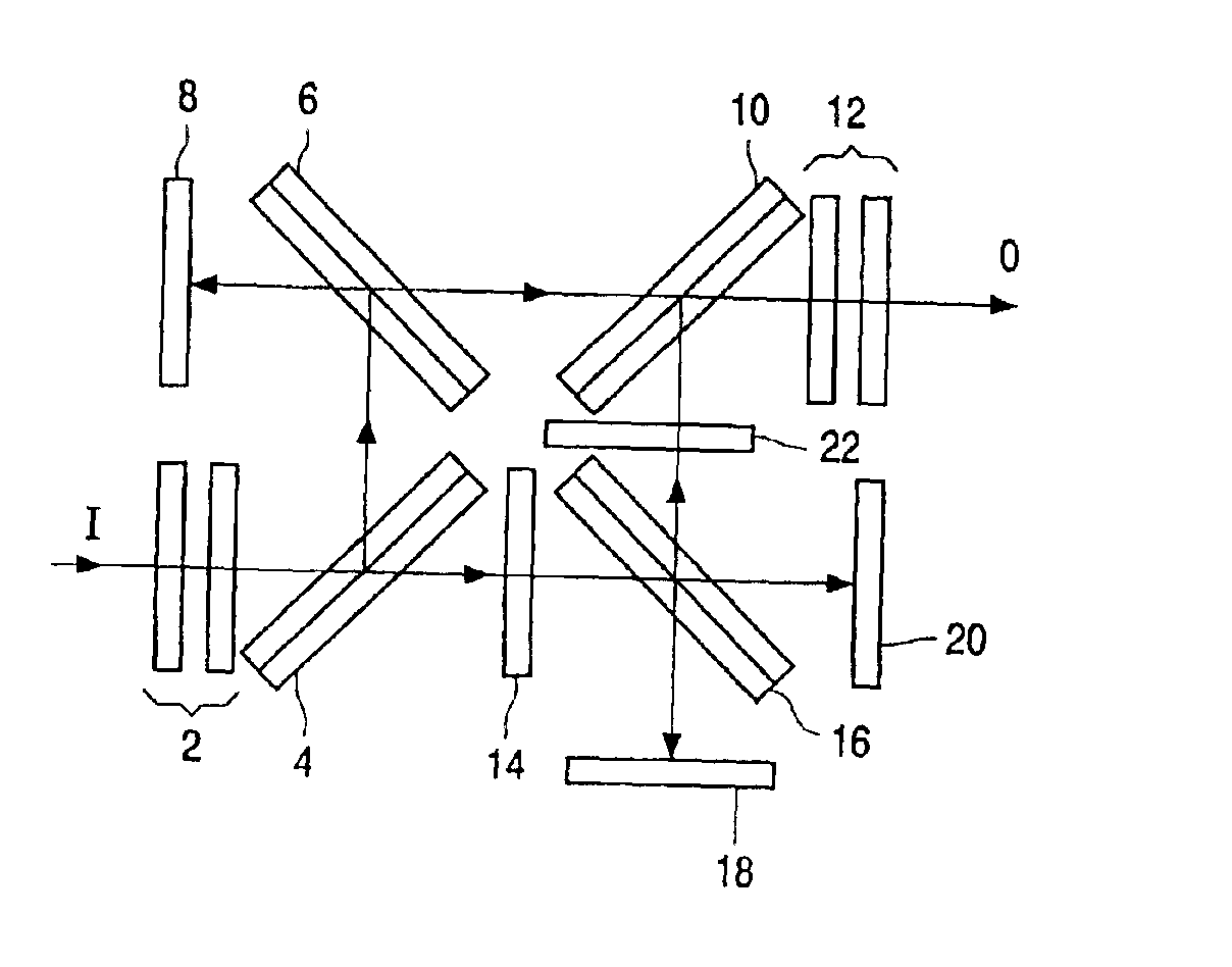
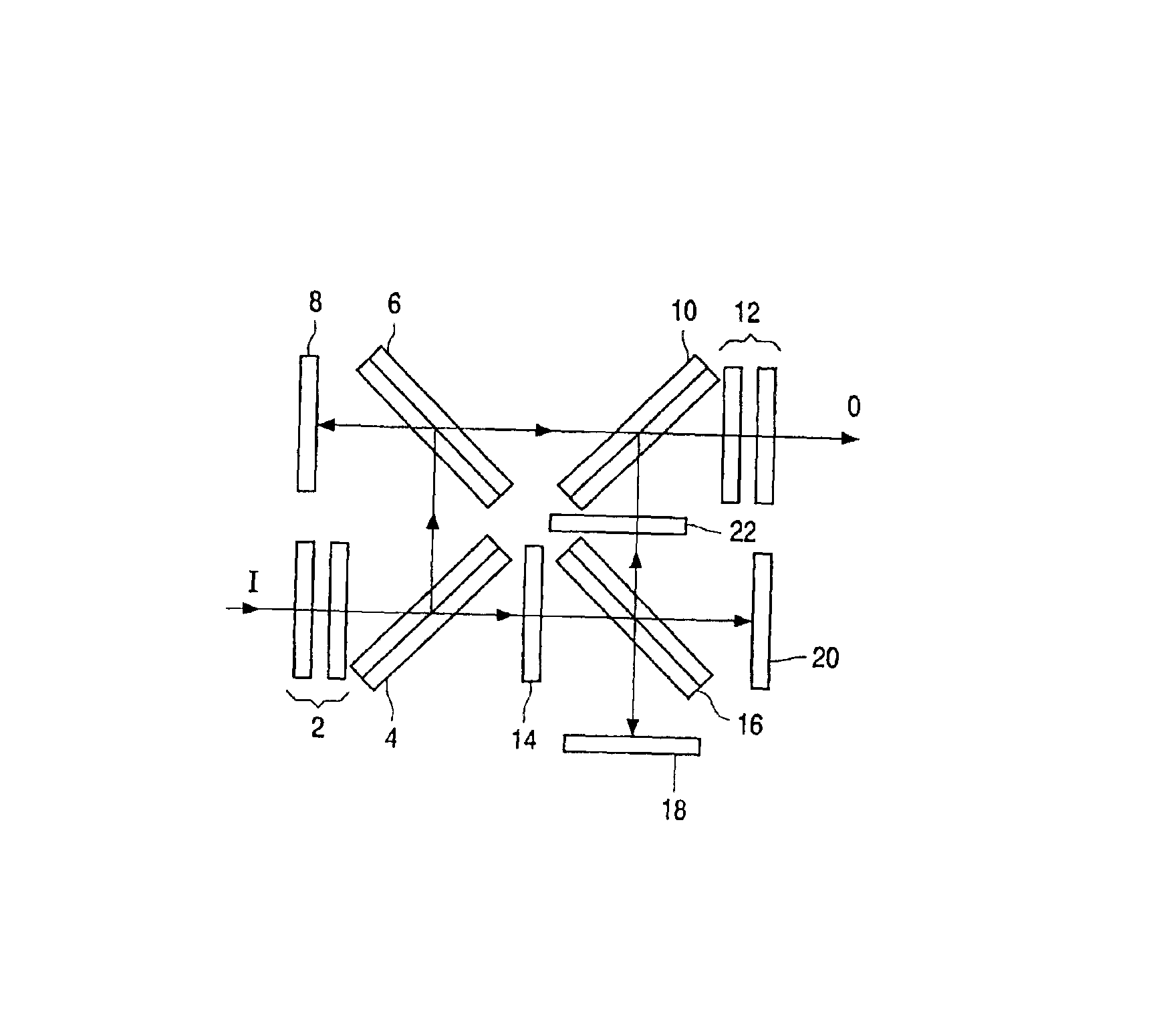
The FIGURE shows a colour video projector modulation device in accordance with an embodiment of the invention. A colour video projector in accordance with this embodiment of the invention includes the modulation device along with a radiation emitter, not shown, emitting substantially white light in the form of an input beam (I) and further optical components, not shown, typically including an output lens for projecting the output beam towards a projector screen.

The modulation device includes a green / magenta retardation plate 2, including birefringent layers for selectively polarising the input beam, which is typically plain polarised, to produce a first component, which consists substantially exclusively of wavelength in the green part of the spectrum and has a first polarisation, and a second component, which consists substantially fully of radiation in the magenta part of the spectrum, which is orthogonally polarised. A first polarising beam splitter 4 splits the different compone...


PUM


Abstract

An optical device for processing radiation that includes a beam splitter and a plurality of radiation processing parts arranged to process the characteristics of different radiation components separately, The polarizing beam splitter includes a wire grid polarizer, a first transparent plate arranged adjacent one side of the polarizer and a second transparent plate arranged adjacent the other side. Each of the first and second plates have substantially equal optical thickness profile.

Description

FIELD OF THE INVENTIONThis invention relates to optical devices for processing radiation, in particular but not exclusively colour projection devices, and to polarising beam splitters.BACKGROUNDColour projection systems are known in the prior art. Consumer products, such as rear projection televisions, rear projection monitors and front projection systems are proposed in which liquid crystal on silicon (LCOS) micro displays are used. Several optical architectures exist for use with three LCOS panels, one each for red, green and blue. Achieving high contrast in a compact and cost-effective system remains problematic.One existing architecture, referred to as the Color Quad™ architecture, proposed by Color Link uses four polarising beam splitter cubes in a square arrangement together with selectively polarising retardance plates such as the Color Select™ plates produced by the same company, to perform the colour splitting and polarisation functions necessary in an LCOS projection syste...

Claims


Application Information

Patent Timeline
Patent Type & Authority Patents(United States)
IPC IPC(8): G02B5/18G02B5/30H04N9/31G03B21/00
CPCG02B5/3058H04N9/3197H04N9/3167H04N9/3105
Inventor DE VAAN, ADRIANUS JOHANNES STEPHANES MARIAMCCLAIN, STEPHEN CHARLES
Owner KONINKLIJKE PHILIPS ELECTRONICS NV
Why Eureka
Try Eureka