Objective lens for optical discs

a technology of optical discs and objects, applied in the field of objects, can solve the problems of insufficient spot diameter, unexpected large aberration, low light intensity of beam spots, etc., and achieve the effect of reducing the intensity of the side lobes around the center of the beam spots and preventing the increase of the intensity of the side lobes

Inactive Publication Date: 2005-03-29
KONICA MINOLTA INC
View PDF10 Cites 5 Cited by
  • Summary
  • Abstract
  • Description
  • Claims
  • Application Information

AI Technical Summary

Benefits of technology

Optionally, at least one of the first annular zones is formed in the vicinity of the boundary between the inner area and the outer area. By forming the first annular zones at the position, intensity of “side lobes” occurring around the center of the beam spot can be prevented from increasing.
Further optionally, the outer area includes a second annular zone which is fo

Problems solved by technology

Therefore, the use of the conventional DVD/CD compatible objective lens inevitably results in low light intensity of the beam spot compared to the case of the ordinary objective lenses distributed to only one type of optical disc.
However, extending the inner area is accompanie

Method used


Image

  • Objective lens for optical discs
  • Objective lens for optical discs
  • Objective lens for optical discs

Examples


example 1

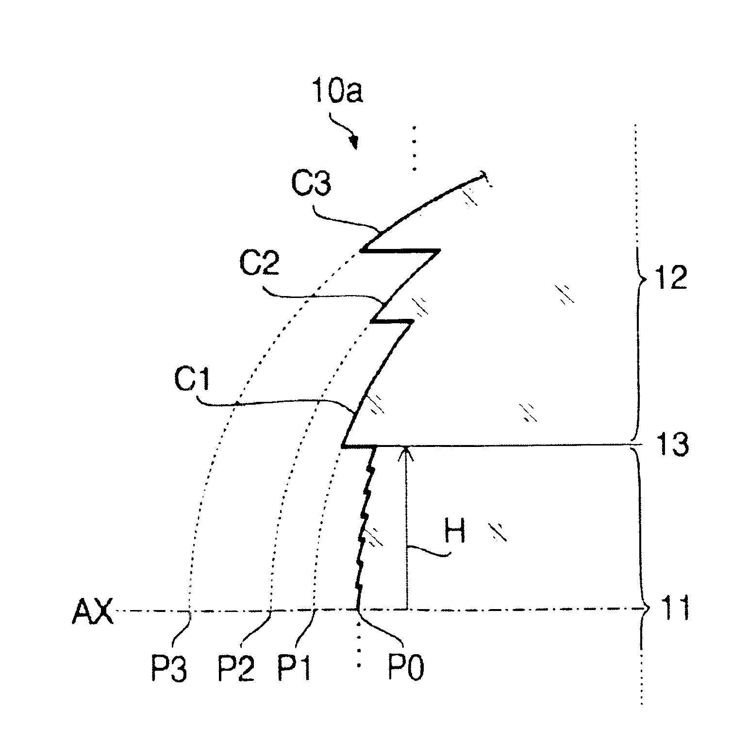
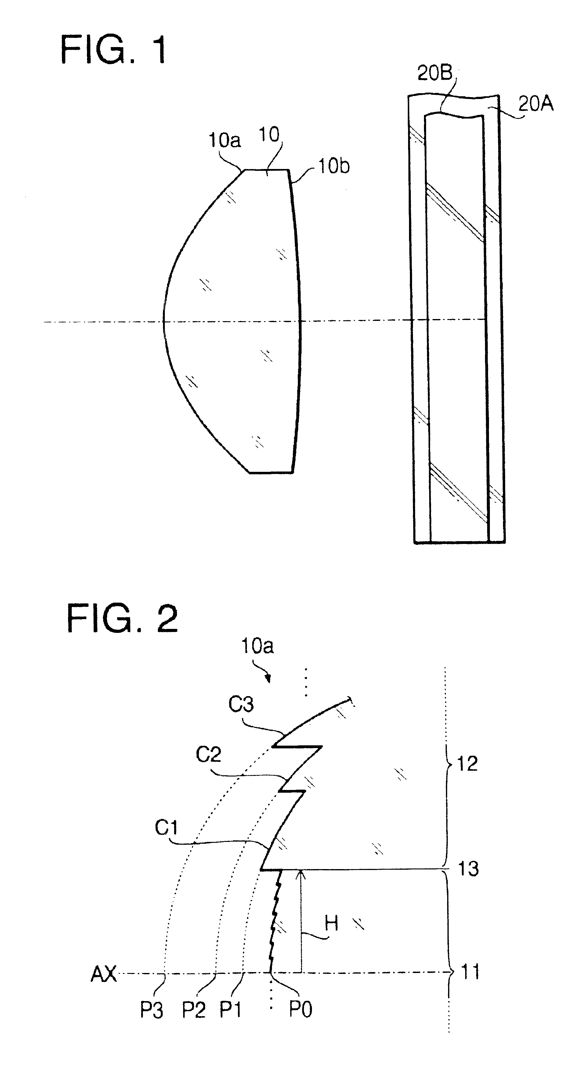
FIG. 1 shows the sectional form of the objective lens 10 of the first example. A second example, which will be described later, also has a similar sectional form. Specific numerical configuration of the objective lens 10 of the first example is shown in the following Table 1.

TABLE 1Optical Disc20A20BDesign Wavelength785nm655nmCentral Thickness1.40 mmFocal Length2.42mm2.40mmDesign NA0.510.65

In the Table 1, the “design wavelength” is the wavelength that is most suitable for the recording / readout of the optical disc (20A, 20B). The numerical configuration shown in 1 applies also to the second example. The following Table 2 shows the height range (hmin-hmax [mm]) from the optical axis AX) of the inner area 11 and that of each annular zone formed in the outer area 12.

TABLE 2hmin ≦ h < hmaxInner Area 110.000 ≦ h < 1.314Outer Area 12Zone C11.314 ≦ h < 1.365Zone C21.365 ≦ h < 1.430Zone C31.430 ≦ h < 1.443Zone C41.443 ≦ h < 1.453Zone C51.453 ≦ h < 1.467Zone...

example 2

The specific numerical configuration, the functions specifying the aspherical shape of the second surface 10b, and the optical path difference function coefficients of the objective lens 10 of the second example are similar to those of the first example, and thus repeated description thereof is omitted for brevity. The following Table 8 shows the height range (hmin-hmax [mm]) from the optical axis AX) of the inner area 11 and that of each annular zone in the outer area 12 of the objective lens of the second example.

TABLE 8hmin ≦ h < hmaxInner Area 110.000 ≦ h < 1.326Outer Area 12Zone C11.326 ≦ h < 1.350Zone C21.350 ≦ h < 1.417Zone C31.417 ≦ h < 1.435Zone C41.435 ≦ h < 1.446Zone C51.446 ≦ h < 1.456Zone C61.456 ≦ h < 1.470Zone C71.470 ≦ h < 1.520Zone C81.520 ≦ h < 1.560

As shown in Table 8, the outer area 12 of the objective lens 10 of the second example includes eight annular zones C1-C8. In Table 8, the value shown at “hmax” of the in...


PUM


Abstract

An objective lens for a plurality of types of optical discs is provided with a diffracting structure on at least one surface thereof. The surface includes an inner area including the optical axis and an outer area. The outer area includes at least one special annular zone. Part of a first beam (having a first wavelength for a first optical disc of lower data density) passed through the zone will be substantially in antiphase with part of the first beam passed through the inner area. The convergence angle θ of part of the first beam incident on the outermost part of the inner area measured after emerging from the objective lens and a design numerical aperture NAref of the first optical disc satisfy:
1.0<sin θ/NAref<1.1.
The effective NA of the objective lens for the first beam is substantially equal to the design numerical aperture NAref.

Description

BACKGROUND OF THE INVENTIONThe present invention relates to an objective lens which is used for an optical disc drive capable of recording / reading data to / from two or more types of optical discs having different data densities and cover layer thicknesses.There exist many types of optical discs according to various standards with different data densities and different thicknesses of the cover layer (protective layer). For instance, DVD (Digital Versatile Disc) has higher record density and a thinner cover layer than CD (Compact Disc). Therefore, when an optical disc loaded on an optical disc drive is replaced with another optical disc of a different type (standard), another effective beam diameter suitable for data density of the new disc has to be attained for reading / writing information while properly correcting spherical aberration which changes depending on the cover layer thickness.For example, for realizing the information recording / readout on optical discs having high data den...

Claims


Application Information

Patent Timeline
IPC IPC(8): G02B13/18G02B13/00G02B3/02G11B7/135G11B7/00G11B7/1353G11B7/1374G11B7/1378
CPCG11B7/1353G11B7/1378G11B7/1374G11B2007/0006
Inventor TAKEUCHI, SHUICHI
Owner KONICA MINOLTA INC
Why Eureka
Try Eureka