Fiber devices with transverse-pressure-controlled squeezers

a technology of fiber devices and squeezers, applied in the direction of optics, optical waveguide light guides, instruments, etc., can solve the problems of back reflection and insertion loss, high signal loss, complicated techniques, etc., to reduce irregularities, minimize the possibility of optical fiber breakage, and minimize the voltage needed

Inactive Publication Date: 2005-03-29
LUNA INNOVATIONS
View PDF12 Cites 27 Cited by
  • Summary
  • Abstract
  • Description
  • Claims
  • Application Information

AI Technical Summary

Benefits of technology

The present invention describes an improved polarization control system for controlling the polarization of light in an optical fiber. The systems uses various mechanisms such as piezoelectric drivers to control a fiber squeezing surface that applies a transverse compressive force to a segment of optical fiber. In one embodiment of the invention, the piezoelectric driver is driven at a resonance frequency to minimize the voltages needed to operate the piezoelectrics. The fiber-squeezing surface are preferably super polished to reduce irregularities below 100 microns. To minimize the possibility of optical fiber breakage, a polyimide coating is applied on the cladding of the fiber.

Problems solved by technology

Such techniques are complicated and require careful alignment.
Redirecting the polarization corrected light back into the optical fiber also results in back reflections and insertion losses.
Although the principles of using pressure on a fiber to control polarization are well documented, one problem with building such systems is high signal losses caused by fiber squeezing.
The activation-induced loss causes errors in the feedback signal and directly degrades the performance of the compensation apparatus.
When a polarization controller is used in an instrument for measuring the polarization dependent loss (PDL) of optical components, the activation-induced loss limits the resolution and accuracy of the measurement.
Controller PDL also contributes to error in the feedback system for PDL measurements and complicates the design of compensation hardware and software.
Current pressure based polarization controllers also suffer reliability problems because the applied pressure causes fiber fracturing and breakage.
However, uniform metal coatings are not easily reproducible in production.
Another problem with prior art fiber squeezing systems is that high voltages are needed to drive the piezoelectric actuators that move the squeezers.
Thus the driver circuits of the piezoelectric actuators require large power supplies and transformers to “step up” the voltages.
These additional components increase the size and cost of the polarization controllers.

Method used


Image

  • Fiber devices with transverse-pressure-controlled squeezers
  • Fiber devices with transverse-pressure-controlled squeezers
  • Fiber devices with transverse-pressure-controlled squeezers

Examples


first embodiment

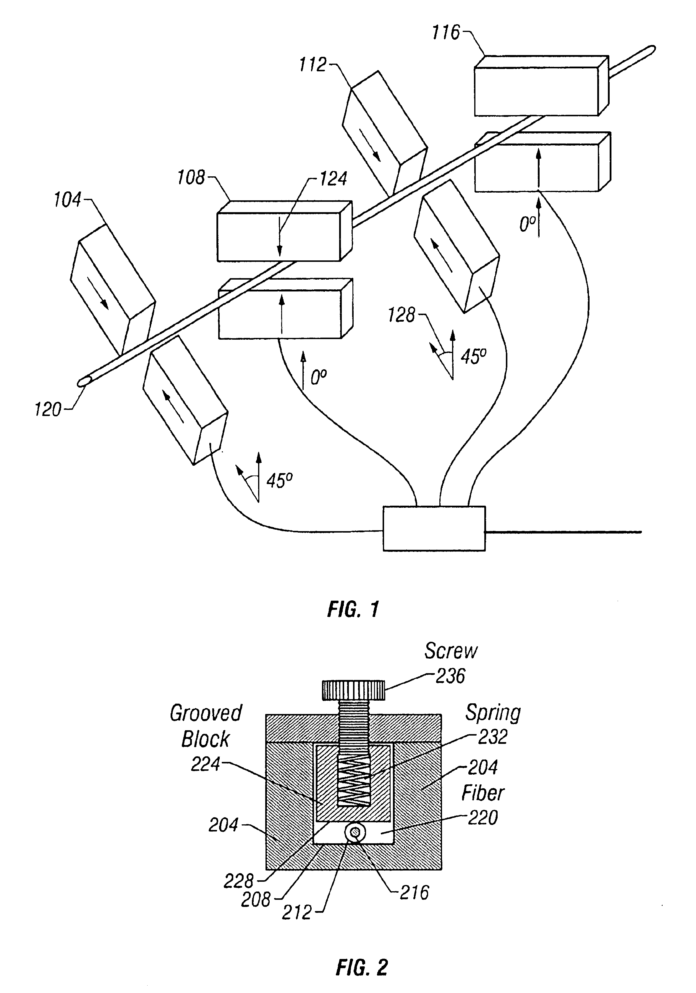
Various mechanisms may be used to control the pressure applied by pressure block 224 to optical fiber 220. In a first embodiment, a spring 232 maintains a constant force on pressure block 224. The spring 232 typically has a spring constant K such that the force applied by the pressure block is equal to F=KX where X is the distance by which the spring is compressed.

The pressure applied by the spring is adjusted by changing the compression of spring 232. In one embodiment, pressure on spring 232 is controlled by a screw 236. Threads on screw 236 interlock with threads in holder 204 such that rotation of screw 236 moves the screw in and out of holder 204. Rotation of screw 236 in a predetermined direction increases the compression of spring 232 and causes pressure block 224 to press harder against optical fiber 220. The increase in pressure further changes the index of refraction and increases the birefringence of fiber core 216.

second embodiment

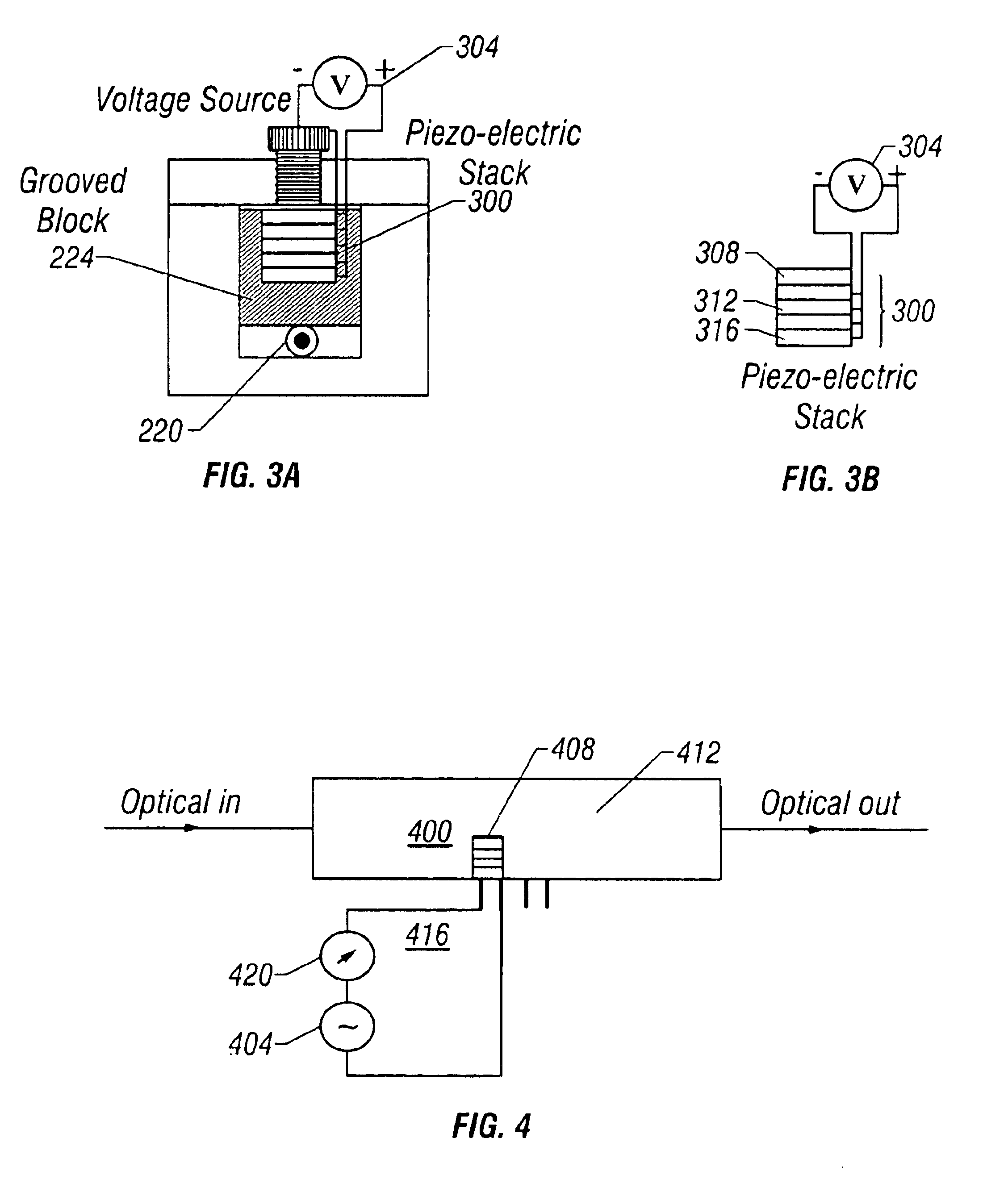
In the invention, a piezo-electric actuator replaces screw236 in moving pressure block 224. FIGS. 3A and 3B illustrate a piezo electric stack 300. A electrical source such as voltages source 304 provides power to stack 300. The stack includes piezo electric elements 308, 312, 316. Altering the voltage applied across stack 300 changes the displacement of stack 300. Substituting screw 236 with piezo electric stack 300 allows a user to use the output voltage of voltage source 304 to control the force applied by pressure block 224.

One difficulty with piezo electric elements such as elements 308, 312, 316 is that significant voltages are typically needed to achieve the desired displacement. Often the voltage requirements may exceed 50 volts. Generating these relatively high voltages in solid state systems involves transformers and powerful power supplies. However, by setting and maintaining the driving frequency of voltage source 304 at the resonant frequency of piezo electric stack 300,...


PUM

PropertyMeasurementUnit
relative orientation angleaaaaaaaaaa
voltageaaaaaaaaaa
heightaaaaaaaaaa

Abstract

Implementations of a polarization control method and apparatus are provided. In one implementation, a device uses super-polished squeezing surfaces to apply pressure against a polyimide coated fiber thereby minimizing micro-bending effects that cause losses in the fiber. Special control circuitry may be used to maintain a driving source of piezo-electrics that control the squeezing surfaces at a resonant frequency, thereby minimizing the voltages needed to drive the piezo-electrics.

Description

BACKGROUND OF THE INVENTIONFiber optic network equipment and test equipment often require careful control of the polarization of light propagating in a fiber optic cable. One method of obtaining such polarization control is to insert a series of wave plates in the light path of the propagating light. However, utilizing wave plates typically involves directing light out of the fiber and redirecting the polarization corrected light back into an optical fiber. Such techniques are complicated and require careful alignment. Redirecting the polarization corrected light back into the optical fiber also results in back reflections and insertion losses.In order to control the polarization of light in a fiber without the losses and alignment problems associated with wave plate systems, several patents describe a technique to control the polarization of light propagating in a fiber by applying pressure to an optical fiber. These references include U.S. Pat. No. 4,988,169 entitled “Optical Sign...

Claims


Application Information

Patent Timeline
Patent Type & Authority Patents(United States)
IPC IPC(8): G02F1/01G02B6/10G02B6/34
CPCG02B6/105G02F1/0136G02B6/274G02F1/0134G02B6/2766
Inventor YAO, X. STEVE
Owner LUNA INNOVATIONS
Why Eureka
Try Eureka