Network repeater and network next transfer desitination searching method

a network repeater and search method technology, applied in the field of network forwarding devices, can solve problems such as long time, and achieve the effects of reducing the amount of memory for storing a data structure, preventing the increase of read time, and reducing the data read tim

Inactive Publication Date: 2005-03-29
HITACHI LTD
View PDF7 Cites 27 Cited by
  • Summary
  • Abstract
  • Description
  • Claims
  • Application Information

AI Technical Summary

Benefits of technology

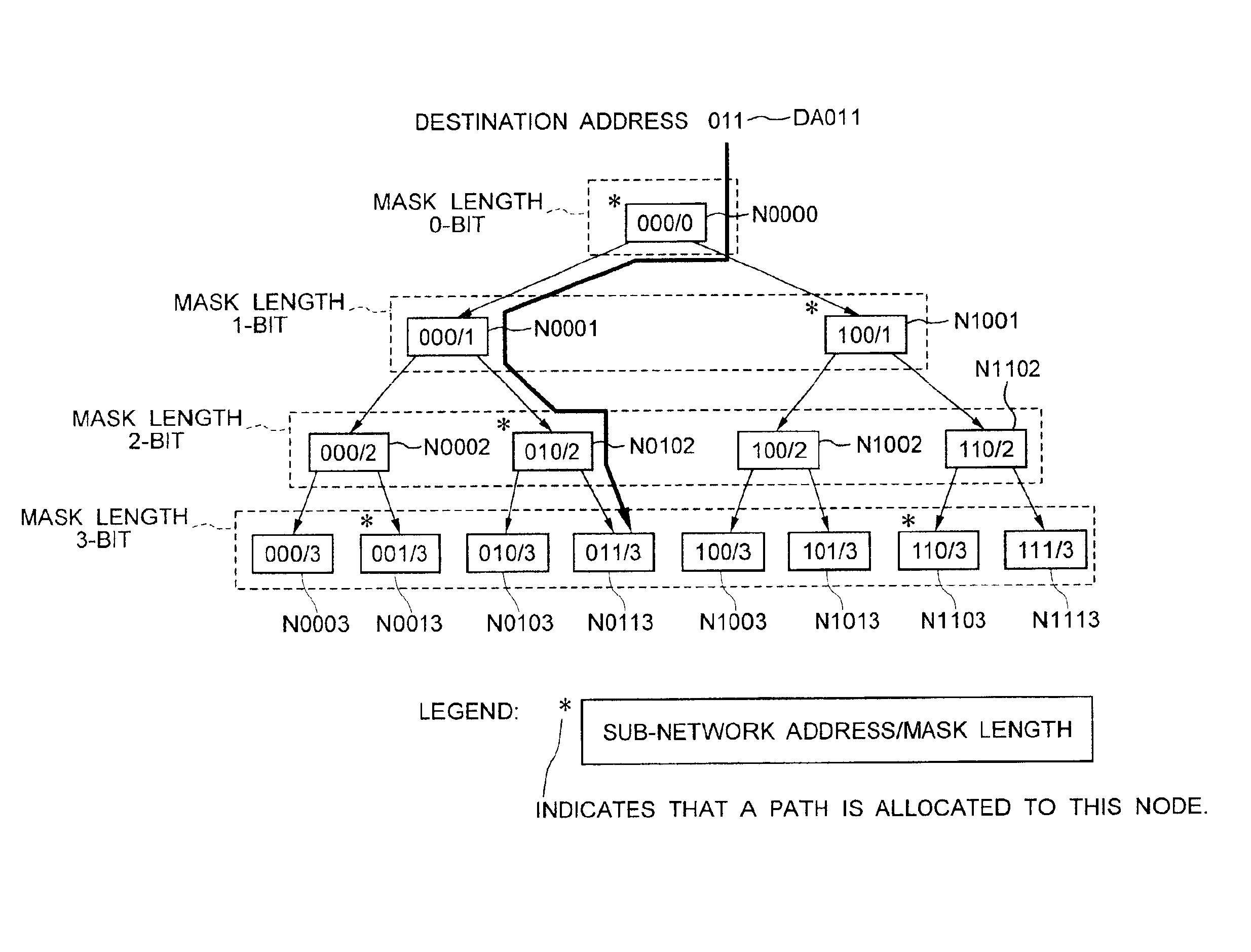
In addition, the number of branches of a node of a search tree, which is two branches in the prior art node, is increased in increments of a power of 2, such as 4-branch tree nodes, 8-branch tree nodes and more. This method increases the number of bits to be tested at a time from one bit for each node to continuous two, three, and more bits, thereby decreasing the number of nodes to be followed until the end of search.
In addition, to reduce the amount of memory for storing a data structure representing a search tree when configuring a 4-branch tree, an 8-branch tree, and more in general, a 2P-branch tree, a total of (2P−1) 2-branch tree nodes, composed of one 2-branch tree node and immediately lower 2-branch tree nodes of (p−1) levels, are combined into one 2P-tree node and, into the combined lowest-level 2(p−1) 2-branch tree nodes, path data allocated to higher-level nodes is embedded to form the 2P-tree node with 2(p−1) 2-branch tree nodes. Furthermore, only one copy of a sharable element is provided.
In addition, when a 4-branch tree node, 8-branch tree node, or more-branch tree node composed of a plurality of 2-branch tree nodes is read for search, only a required part, not the whole, of the node is read to prevent the read time from increasing as the node becomes larger. To select only the required part of node data, node mask length information is necessary before the node data is read. Thus, each node contains the mask length of the immediately-lower node. Furthermore, at the start of each node, a flag indicating whether or not a path is allocated to the node is provided. This flag is read first to prevent path information for a node, to which a path is not allocated, from being read. This reduces the data read time.

Problems solved by technology

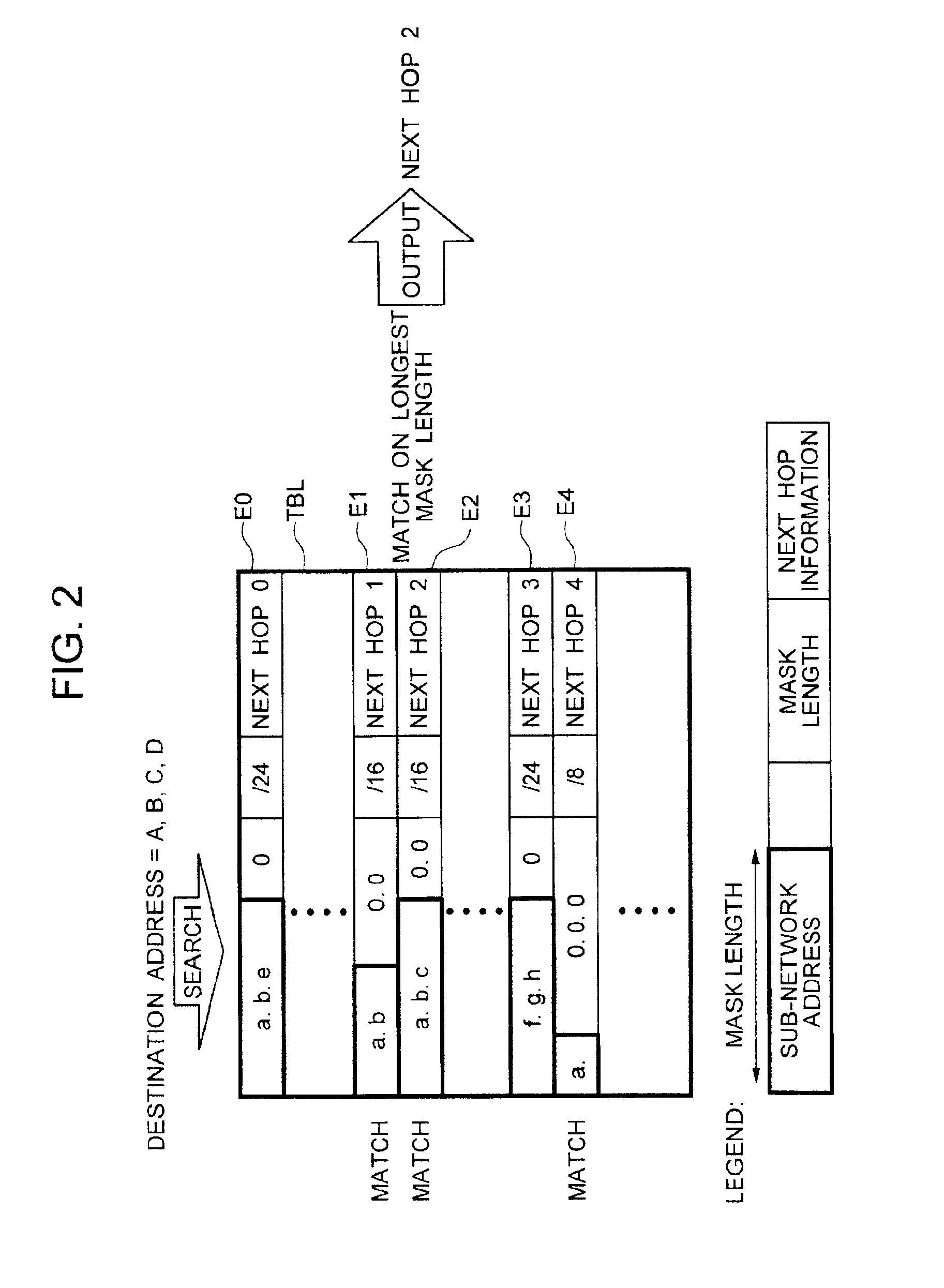
As described above, the problem with the Radish algorithm is that it takes long because the algorithm checks destination addresses from the top downward, one bit at a time, to search for a path.

Method used


Image

  • Network repeater and network next transfer desitination searching method
  • Network repeater and network next transfer desitination searching method
  • Network repeater and network next transfer desitination searching method

Examples


Embodiment Construction

To describe the present invention more in detail, the best mode for carrying out the present invention will be described with reference to the attached drawings.

First, the typical configuration of a router to which the present invention applies will be described with reference to FIG. 38. In FIG. 38, number 100 is a router, number 110 is a routing controller, number 120 is a router bus, number 130 is a network interface, number 140 is a port, and number 150 is a sub-network.

The network interface 130 receives a packet from a sub-network connected to the port 140 and sends the received packet to the routing controller 110 via the router bus 120. The routing controller 110, with a routing table in which routing information is stored, checks the destination of the received packet with the use of the routing information to determine the sub-network 150 to which the packet is to be forwarded, and sends the packet to the network interface 130 of the port 140 to which the sub-network 150 is...


PUM


Abstract

The present invention improves a network forwarding device, such as a router, in a computer network system. When an address to which a received packet is to be forwarded is searched for based on path information, a path search data structure is changed to the one in which, in a 2-branch tree search in which a destination address of the received packet is checked, one bit at a time beginning at a highest-order bit, p (p is an integer equal to or larger than 2) levels are combined into one 2P-branch tree to perform a search of the p levels of the 2-branch tree as a one-level search. This data structure speeds up path search processing.

Description

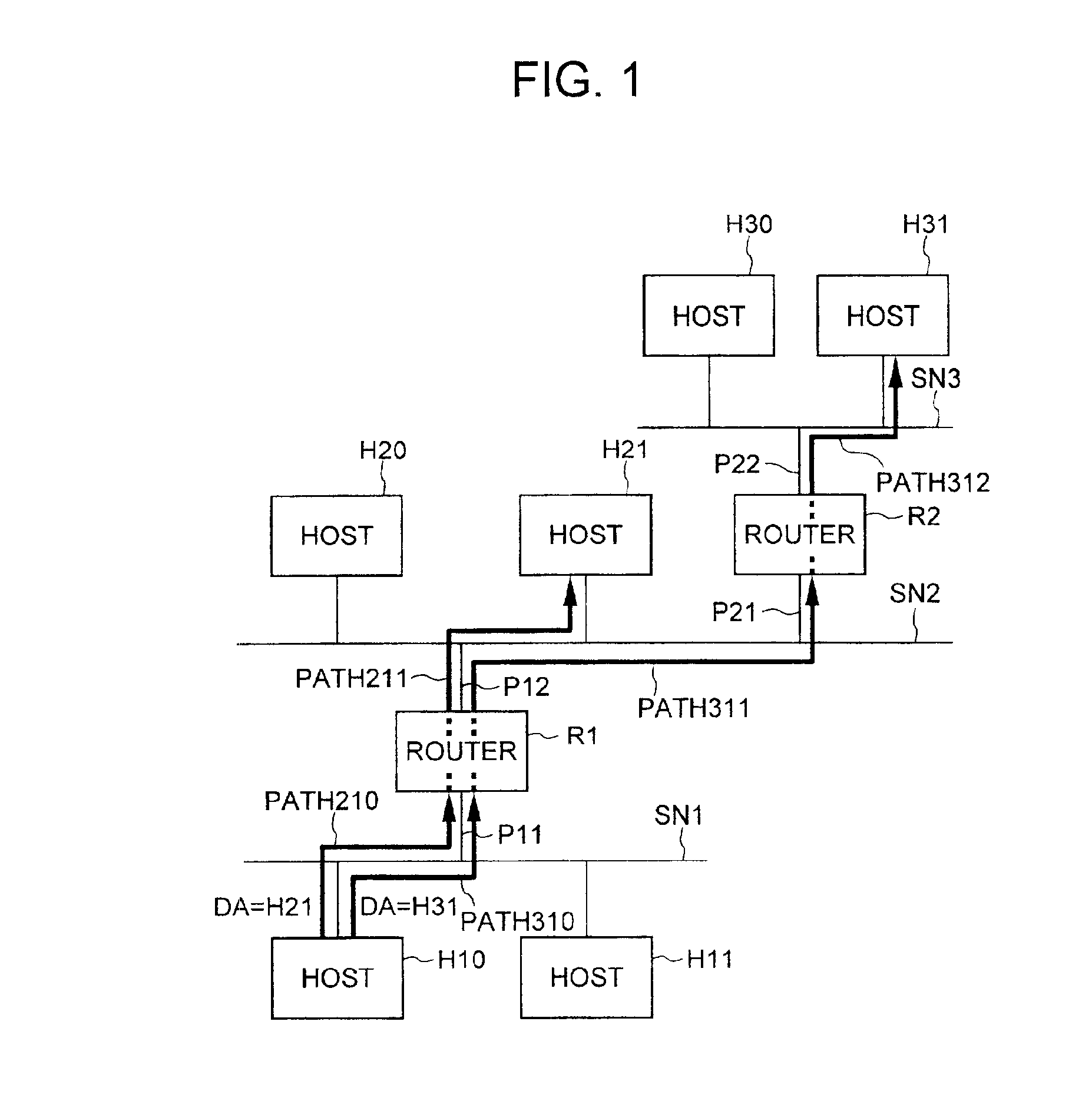
TECHNICAL FIELDThe present invention relates to a network forwarding device such as a router on a computer network system. More particularly, the present invention relates to a network forwarding device and a network next-hop search method for quickly searching for an address to which a packet, received by a network forwarding device, is to be forwarded based on the destination address contained in the packet.BACKGROUND ARTIn a network system, network forwarding devices such as routers are used to connect a plurality of subnets. A router checks the destination address of a packet received from a subnet to which the router is connected, determines the next hop, and forwards the received packet to the subnet to which the next-hop router or the host is connected. FIG. 1 shows the configuration of a general network system composed of a plurality of subnets connected by routers.In FIG. 1, R1 and R2 are routers, SN1 is a sub network connected to port P11 of router R1, SN2 is a sub network...

Claims


Application Information

Patent Timeline
Patent Type & Authority Patents(United States)
IPC IPC(8): H04L12/56G06F17/30H04L12/66H04L45/748
CPCH04L45/742H04L45/48H04L45/00
Inventor SUGAI, KAZUOAIMOTO, TAKESHIMATSUYAMA, NOBUHITOAKAHANE, SHINICHITANABE, NOBORUSAKO, YOSHIHITO
Owner HITACHI LTD
Why Eureka
Try Eureka