Single-die injection pump for a common rail fuel injection system

a fuel injection system and injection pump technology, applied in the direction of pump parameters, piston pumps, positive displacement liquid engines, etc., can solve the problems of production costs and increase, and achieve the effects of reducing idle volume and leakage losses, shortening opening times, and reducing idle volum

Inactive Publication Date: 2005-04-05
ROBERT BOSCH GMBH
View PDF8 Cites 7 Cited by
  • Summary
  • Abstract
  • Description
  • Claims
  • Application Information

AI Technical Summary

Benefits of technology

In another feature of the invention, the pump cylinder is embodied as a blind bore, so that the idle volume and leakage losses are further reduced. The quantity regulation of the injection pump, by varying the prestroke of the piston, also contributes to reducing the idle volume. By means of this quantity regulation, the piston always pumps up to top dead center (TDC), so that the idle volume becomes minimal.
In another feature of the invention, it is provided that the outlet can be sealed off by a sealing seat between the housing and the control piston, and that the diameter of the sealing seat is less than the diameter of a receiving bore in the housing for the control piston, so that the opening motion of the control piston is reinforced by the fuel that is under pressure. It is also possible that the opening motion of the quantity control valve is reinforced by a spring, so that a shortening of the opening times and improved starting performance of the engine are achieved. Moreover, the pressure forces on the low-pressure side can be largely compensated for, in a variant, by means of two piston faces of approximately equal size.
Further variants of the invention provide that the longitudinal axis of the control piston forms an angle of 90° with the longitudinal axis of the piston, and / or that a pressure relief chamber acting as a low-pressure reservoir is provided in the outlet, so that an especially compact design with a correspondingly slight idle volume is achieved, and that the low-pressure reservoir reinforces the filling of the pump cylinder during the intake stroke. This provision also prevents cavitation.
By the use of ceramic for the piston and a possibly present tappet roller, the forces of inertia can be reduced, thus reducing the load on the injection pump. Moreover, because of the good wear and deformation performance of ceramic, the play between piston and cylinder can be decreased, thus further increasing the volumetric efficiency.
In a further feature of the invention, it is provided that a common rail is integrated with the housing, so that the idle volume is reduced still further.
In still another feature of the invention, the pumping stroke of the injection pump is phase-offset in a way synchronized with injection at the instant of injection of the engine. Depending on how great a phase offset is selected, any pressure surges that may occur in a high-pressure region of the injection pump can be utilized to build up the highest possible injection pressure, or else the injection takes place at an instant when there are no pressure surges, or pressure surges of only a slight extent. In the second variant, the fuel metering precision upon injection is improved.

Problems solved by technology

With the number of pump cylinders, the production costs also rise.
Because of the large temporary pumping quantity and the resultant peak torque value, and the previously unsolved problem of filling the pump cylinder in a very short time, until now single-die injection pumps were not used to supply fuel in common rails of internal combustion engines that have more than one cylinder.

Method used


Image

  • Single-die injection pump for a common rail fuel injection system
  • Single-die injection pump for a common rail fuel injection system
  • Single-die injection pump for a common rail fuel injection system

Examples


Embodiment Construction

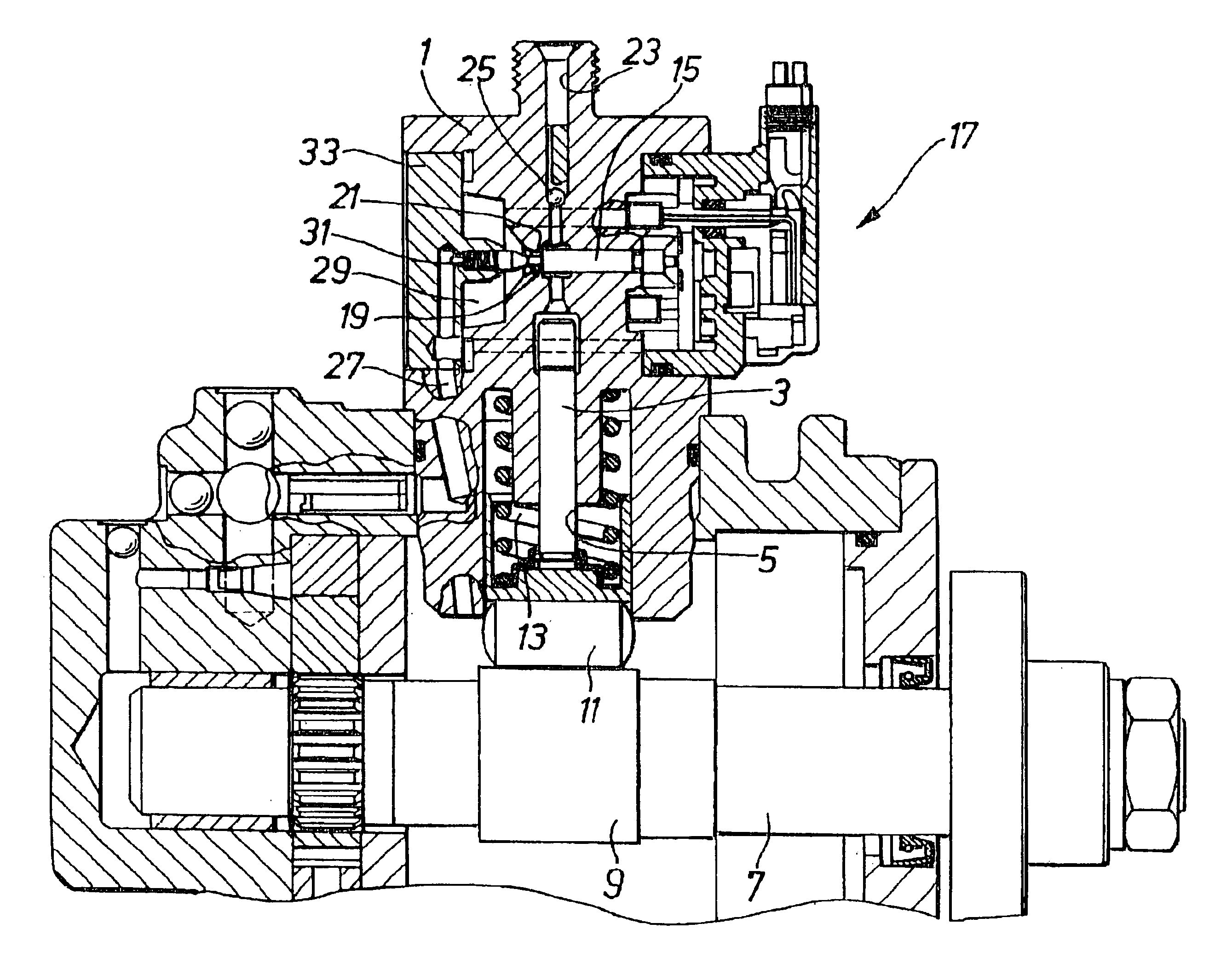
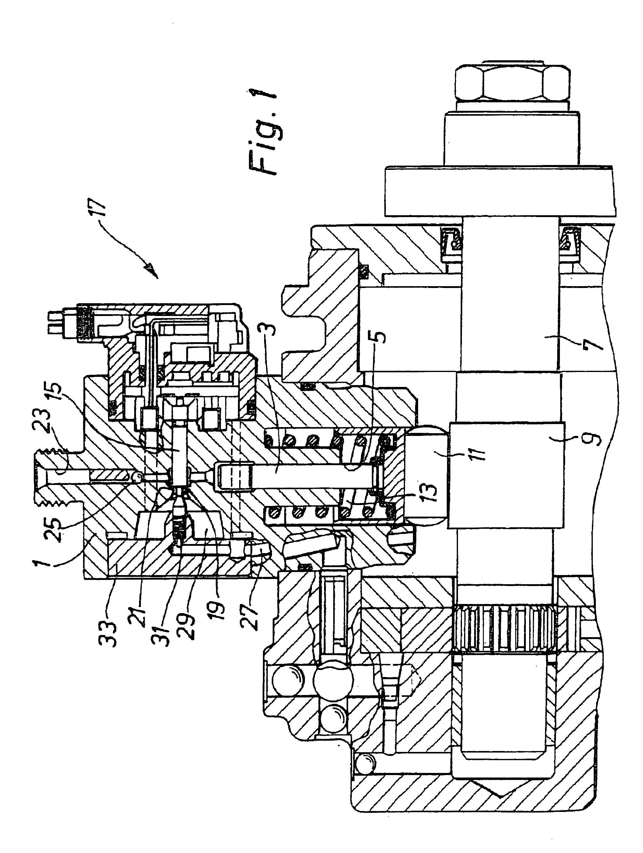
FIG. 1 shows a first exemplary embodiment of a single-die injection pump of the invention. In a housing 1, a piston 3 is guided by a pump cylinder 5. The piston 3 is driven by a camshaft 7. An eccentric portion 9 of the camshaft 7 acts via a tappet roller 11 on the piston 3. The eccentric portion is a cam, in terms of the invention. However, the cams can also have other geometries than an eccentrically disposed circle. The piston 3 is pressed against the tappet roller 11 via a restoring spring 13 represented only symbolically.

Above the pump cylinder 5 in the housing 1, a control piston 15 of a quantity control valve 17 embodied as a magnet valve is disposed perpendicular to the longitudinal axis of the pump cylinder 5. The control piston 5 has a shoulder 19, which together with a correspondingly embodied heel 21 forms a sealing seat. When the quantity control valve 17 is closed, the shoulder 19 rests on the heel 21, and the fuel pumped by the piston 3 is pumped into a high-pressure ...


PUM


Abstract

A single-die injection pump for high-speed internal combustion engines which, because of its compact design and good volumetric efficiency, in conjunction with a high oscillation frequency of the piston, has a pumping quantity comparable to a multiple-die injection pump, without causing excessively high peak torque values in the drive of the single-die injection pump.

Description

BACKGROUND OF THE INVENTION1. Field of the InventionThe invention relates to an injection pump for a common rail fuel injection system of an internal combustion engine, having a pump cylinder, disposed in a housing, having a piston oscillating in the pump cylinder, wherein the pressure of the fuel aspirated from a fuel inlet into the pump cylinder is increased by the piston, and having a quantity control valve, wherein the quantity control valve has a directly triggered control piston integrated with the housing, and the quantity control valve controls the pumping flow of the piston into an outlet or a high-pressure bore communicating with a common rail.2. Description of the Prior ArtThe injection pump known from German Published, Nonexamined Patent Application DE-OS 42 21 921 A1 is suitable for use in internal combustion engines with more than one cylinder only if it has a number of pump cylinders corresponding to the number of engine cylinders. With the number of pump cylinders, t...

Claims


Application Information

Patent Timeline
Patent Type & Authority Patents(United States)
IPC IPC(8): F02M63/02F02M59/02F02M59/00F02M63/00F04B49/22F04B49/24F02M59/20F02M51/00F02M59/10F02M59/44F04B9/04
CPCF02M59/02F02M63/0225F04B49/243F04B2203/0605F04B2201/0207
Inventor FUCHS, WALTER
Owner ROBERT BOSCH GMBH
Why Eureka
Try Eureka