Turbocharger with reduced coking

a turbocharger and coking technology, applied in the field of turbochargers, can solve problems such as inability to achieve solutions, and achieve the effect of increasing the weight or volume of the turbocharger and greatly reducing the coking

Inactive Publication Date: 2005-04-05
BORGWARNER INC
View PDF8 Cites 42 Cited by
  • Summary
  • Abstract
  • Description
  • Claims
  • Application Information

AI Technical Summary

Benefits of technology

Following experimentation the inventor discovered that coking can in fact be greatly reduced without noticeably increasing weight or volume of the turbocharger by coating at least a part of the wall of the internal space through which lubricant flows with an oil repelling and / or heat insulating coating.

Problems solved by technology

However, given the limited amount of engine compartment space available for installation of mechanical means, and given the requirement for low weight and high efficiency, such a solution did not seem to be achievable.

Method used


Image

  • Turbocharger with reduced coking
  • Turbocharger with reduced coking

Examples


Embodiment Construction

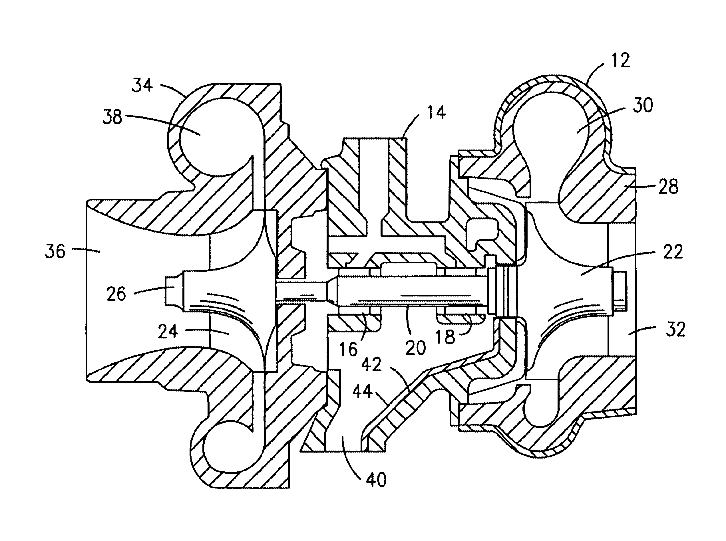
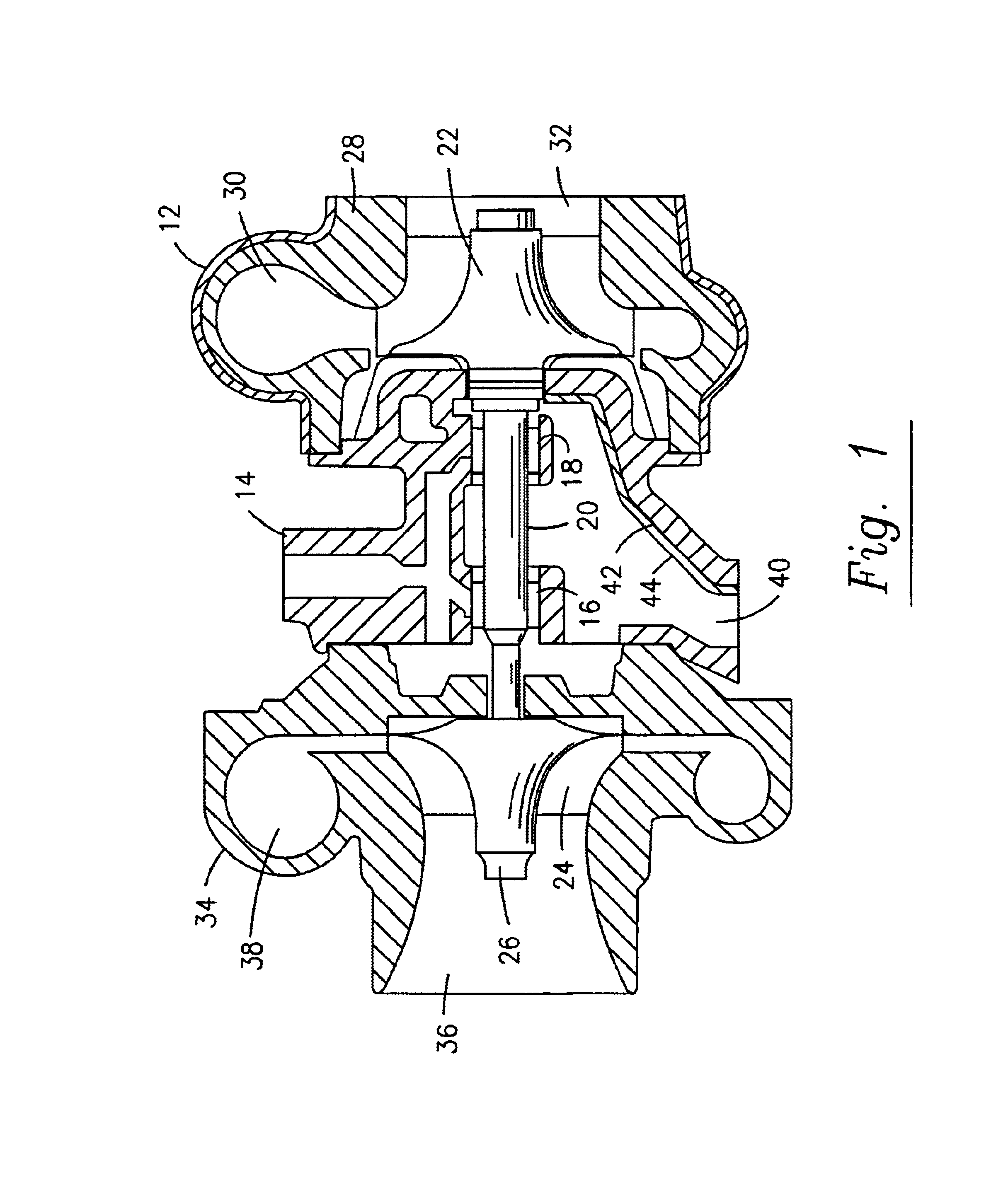
The present invention is applicable to any exhaust gas driven turbocharger, and particularly those lubricated by a lubricant liable to coking. Turbochargers being well known in the art, there is no need herein to go into detail on any specific design of any one turbocharger. The embodiment shown in FIG. 1 shall be considered representative herein of turbochargers in general.

With reference to FIG. 1, a turbocharger 10 includes a housing generally referenced with the numeral 12. Housing 12 includes a center section 14 receiving a pair of spaced apart journal bearings 16, 18, and rotatably receiving therein an elongate shaft 20. A turbine wheel 22 is attached to or integrally formed with one end of shaft 20. At the opposite end of shaft 20 a compressor wheel 24 is carried thereon and drivingly secured thereto by a nut 26 threadably engaging the shaft.

A turbine housing section 28 mates with the bearing housing section 14 and defines an exhaust gas inlet 30 leading to a radially outer po...


PUM

PropertyMeasurementUnit
particle sizeaaaaaaaaaa
melting temperatureaaaaaaaaaa
heat insulatingaaaaaaaaaa

Abstract

A turbocharger including means for preventing or reducing coking, particularly following engine shutdown, without noticeably increasing weight or volume of the turbocharger. The turbocharger bearing housing (14) has defined therein a lubrication flow path for bearing lubricant and a lubricant drain gallery (40) below a shaft (20), and in accordance with the invention at least a portion of a wall (42) of the lubricant drain gallery (40) is coated with an oil repellant and/or heat insulating coating (44).

Description

FIELD OF THE INVENTIONThe present invention concerns a turbocharger including means for preventing or reducing coking, particularly following engine shutdown, without noticeably increasing weight or volume of the turbocharger.DESCRIPTION OF THE RELATED ARTTurbochargers generally include a turbine housing section for directing exhaust gasses from an exhaust inlet to an exhaust outlet across a turbine rotor. The turbine rotor drives a shaft journaled in a bearing housing section. A compressor rotor is driven on the other end of the shaft.Crankcase oil is commonly used to lubricate the rotating bearing interfaces as well as the thrust surfaces that limit axial excursions of the shaft. Temperatures of about 740° C. occur in the exhaust gas turbine in the case of Diesel engines and above about 1,000° C. in the case of Otto-cycle engines. Heat migrating from the turbine housing section and turbine into the shaft and bearing housing raise the temperature high enough to degrade or “coke” th...

Claims


Application Information

Patent Timeline
Patent Type & Authority Patents(United States)
IPC IPC(8): F04D29/02F04D29/00F01D25/12F01D25/08F01D25/18F01D25/00F16C33/04F16C33/10F04D25/02F04D25/04
CPCF01D25/125F01D25/18F04D25/04F04D29/023F16C33/10F16C2360/24F05D2220/40F05D2260/602F05D2230/90F05D2300/432F05D2300/433F05D2300/437F05D2300/50F05D2300/502F05D2300/512F05D2300/611F16C17/02F16C17/18Y10T428/24998
Inventor ROBY, STEVE
Owner BORGWARNER INC
Why Eureka
Try Eureka