
Tiling process for constructing a chemical array

Inactive Publication Date: 2005-04-05
AGILENT TECH INC
View PDF16 Cites 31 Cited by
  • Summary
  • Abstract
  • Description
  • Claims
  • Application Information

AI Technical Summary

Benefits of technology

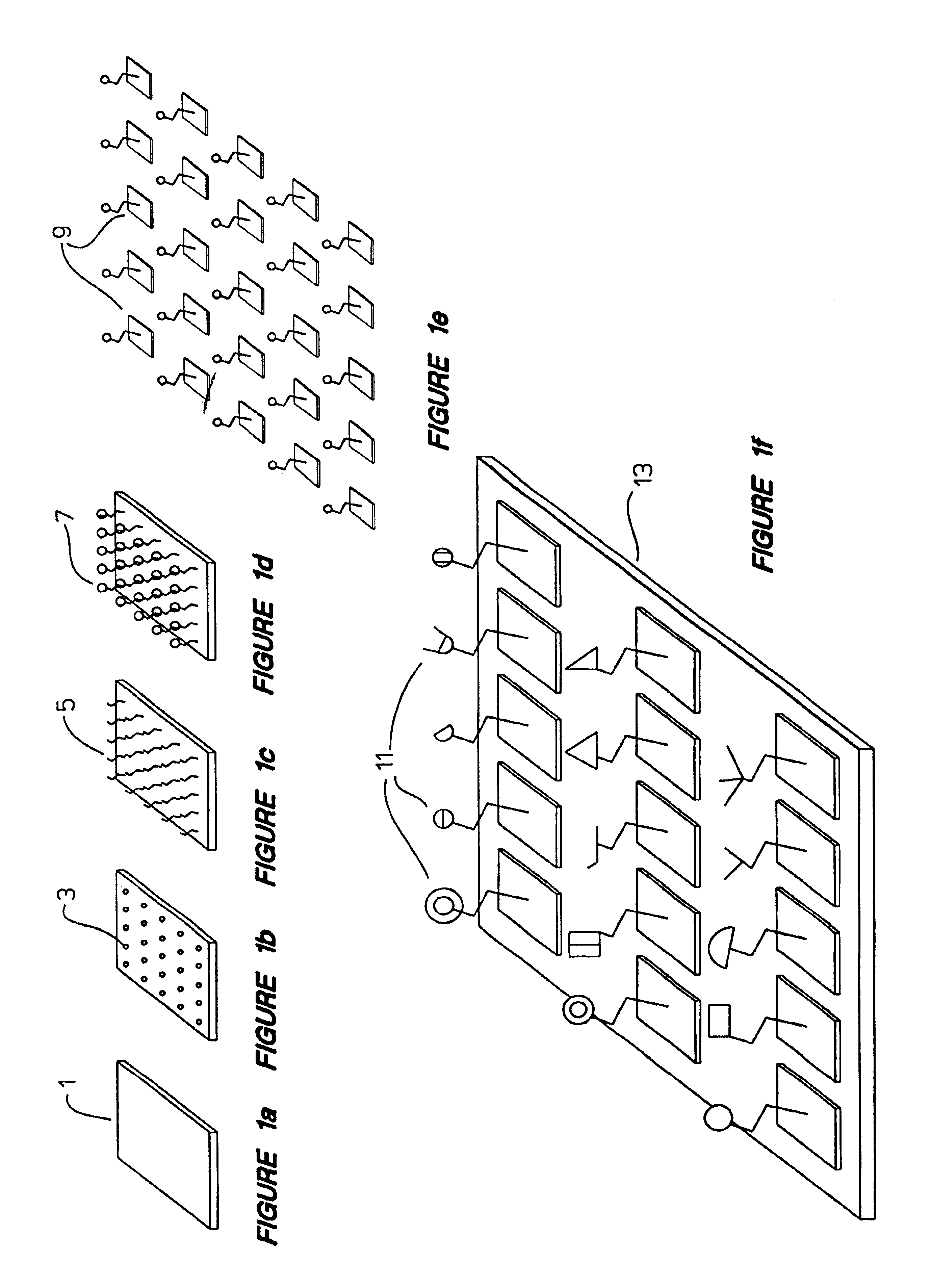
An objective of this invention is to increase the speed and reproducibility of the array manufacturing process by attaching probes to discrete physical entities which can be moved robotically to separate predetermined locations on a support to create the array. The attachment step is preferably carried out in a batchwise manner to optimize the linker chemistry and attachment density of each type of probe in the array independently of the assembly of the array.
Yet another objective of this invention is to streamline the quality control procedure and lower the cost of producing an array with a high degree of chemical complexity. The fidelity of synthesis of each probe type in the array and its density of attachment can be verified prior to tiling the array. The entire surface of a discrete physical entity can be tested prior to subdividing it into hundreds of thousands of tiles for placement into hundreds of thousands of arrays, thereby permitting the early detection and correction of manufacturing problems.

Problems solved by technology

There are disadvantages to forming an array in this manner when the array is comprised of biopolymers such as oligonucleotides.
The in situ method currently used for the commercial manufacture of oligonucleotide arrays is not well suited for the efficient production of arrays of long chain polymer probes because of the number of cycles of elongation required and the variable efficiency of each attachment step.
Although solutions have been devised to shorten the time of the overall process by segregating groups of sites for the simultaneous addition of a given nucleotide (see, e.g., Frank et al., Nucleic Acids Res. 11, 4365-4377 (1983); U.S. Pat. No. 5,510,270), manufacturing an array in this way is inefficient, particularly when the desired array is intended to include hundreds of different probe sequences and probe lengths in excess of 30 nucleotides.
The problems with probe fidelity necessitate a high level of probe redundancy, and it is only after the entire array is formed that defects are discoverable.

Method used


Image

  • Tiling process for constructing a chemical array
  • Tiling process for constructing a chemical array

Examples


Embodiment Construction

Before the invention is described in detail, it is to be understood that this invention is not limited to the particular component parts or process steps of the methods described, as such parts and methods may vary. It is also to be understood that the terminology used herein is for purposes of describing particular embodiments only, and is not intended to be limiting. As used in the specification and the appended claims, the singular forms “a”, “an”, and “the” include plural referents unless the context clearly indicates otherwise.

In this specification and in the claims which follow, reference will be made to a number of terms which are used as defined below.

An “array” is an arrangement of objects in space in which each object occupies a separate predetermined spatial position. Each of the objects in the array of this invention comprise one or more species of chemical moiety attached to a “discrete physical entity”, such that the physical location of each species is known or ascert...


PUM

PropertyMeasurementUnit
Lengthaaaaaaaaaa
Lengthaaaaaaaaaa
Lengthaaaaaaaaaa

Abstract

A process of constructing an array of chemical moieties having the following steps: forming multiple discrete physical entities (tiles) from a substantially planar material having one or more species of chemical moiety attached thereto; and picking and placing the entities (tiles) stably on a support at spatially distinct ascertainable locations to form an array of chemical moieties. The formed array includes at least two species of chemical moiety and preferably from about 50 to about 1000 species. The claimed invention includes an array formed by this process.

Description

TECHNICAL FIELDThis invention relates generally to a process of forming an array of bioorganic molecular probes on a support, and to an array formed by this process.BACKGROUNDArrays of immobilized probes are currently being developed for use in assays to detect and identify components in biological samples and for screening molecular libraries. The ability to screen for multiple species of molecules in a single assay test is particularly valuable for purposes of drug discovery and clinical genetics. Accordingly, array manufacturing technologies have been developed to permit a large number of different probes to be incorporated into an array at separate and known locations (see, e.g., Fodor et al., Science 251, 767-773 (1991); Southern et al., Nucleic Acids Research 22: 1368-1373 (1994); U.S. Pat. No. 5,510,270; U.S. Pat. No. 5,474,796; U.S. Pat. No. 5,429,807; and U.S. Pat. No. 5,472,672). In these prior art methods, the probe molecules are synthesized in situ on a solid support sur...

Claims


Application Information

Patent Timeline
IPC IPC(8): B01J19/00C07B61/00C07K1/00C07K1/04C07K17/02G01N33/48C12M1/00C12Q1/68C40B40/06C40B40/10C40B70/00G01N33/15G01N33/53G01N37/00H01L49/00
CPCB01J19/0046C07K1/045C07K1/047C40B70/00B01J2219/00538B01J2219/0054B01J2219/00547B01J2219/00563B01J2219/00565B01J2219/00585B01J2219/00596B01J2219/00605B01J2219/0061B01J2219/00617B01J2219/00626B01J2219/0063B01J2219/00637B01J2219/00659B01J2219/00662B01J2219/00722B01J2219/00725C07B2200/11C40B40/06C40B40/10B01J2219/00527
Inventor SCHEMBRI, CAROL T.
Owner AGILENT TECH INC
Learn More