Spatial light modulator

a technology of light modulator and polarizing element, which is applied in the field of spatial light modulator, can solve the problems of low operation speed, high manufacturing cost, and reliability problems, and achieve the effects of high operation speed, low power consumption, and excellent magneto-optic performan

Inactive Publication Date: 2005-04-05
OPTWARE
View PDF5 Cites 6 Cited by
  • Summary
  • Abstract
  • Description
  • Claims
  • Application Information

AI Technical Summary

Benefits of technology

An object of the present invention is to provide a spatial light modulator with an excellent magneto-optic performance, a high operation speed and low power consumption.

Problems solved by technology

However, the spatial light modulator using a liquid crystal has a problem that the operation speed is low.
However, since this spatial light modulator is a micro machine manufactured by a highly-developed semiconductor manufacturing process and having a complicated structure, the manufacturing cost is high, and there remains a problem in reliability since it has a mechanical driving portion.
Thus, if the thickness of the magnetic layer is increased, it is necessary to increase the value of the current to be passed through the conductor to reverse the magnetization in each pixel, and as a result, power consumption becomes high.
In such a magneto-optic spatial light modulator, if the thickness of the magnetic layer is increased, it becomes necessary to increase the depths of the grooves formed in the magnetic layer as well, and therefore it becomes difficult to form the grooves.
Further, if the depths of the grooves are increased, it becomes impossible to directly form the conductor on the magnetic layer.
In addition, if the depths of the grooves are increased, it becomes technically difficult to fill the grooves with the insulating material and to flatten the top surface of the magnetic layer.

Method used


Image

  • Spatial light modulator
  • Spatial light modulator
  • Spatial light modulator

Examples


first embodiment

[First Embodiment]

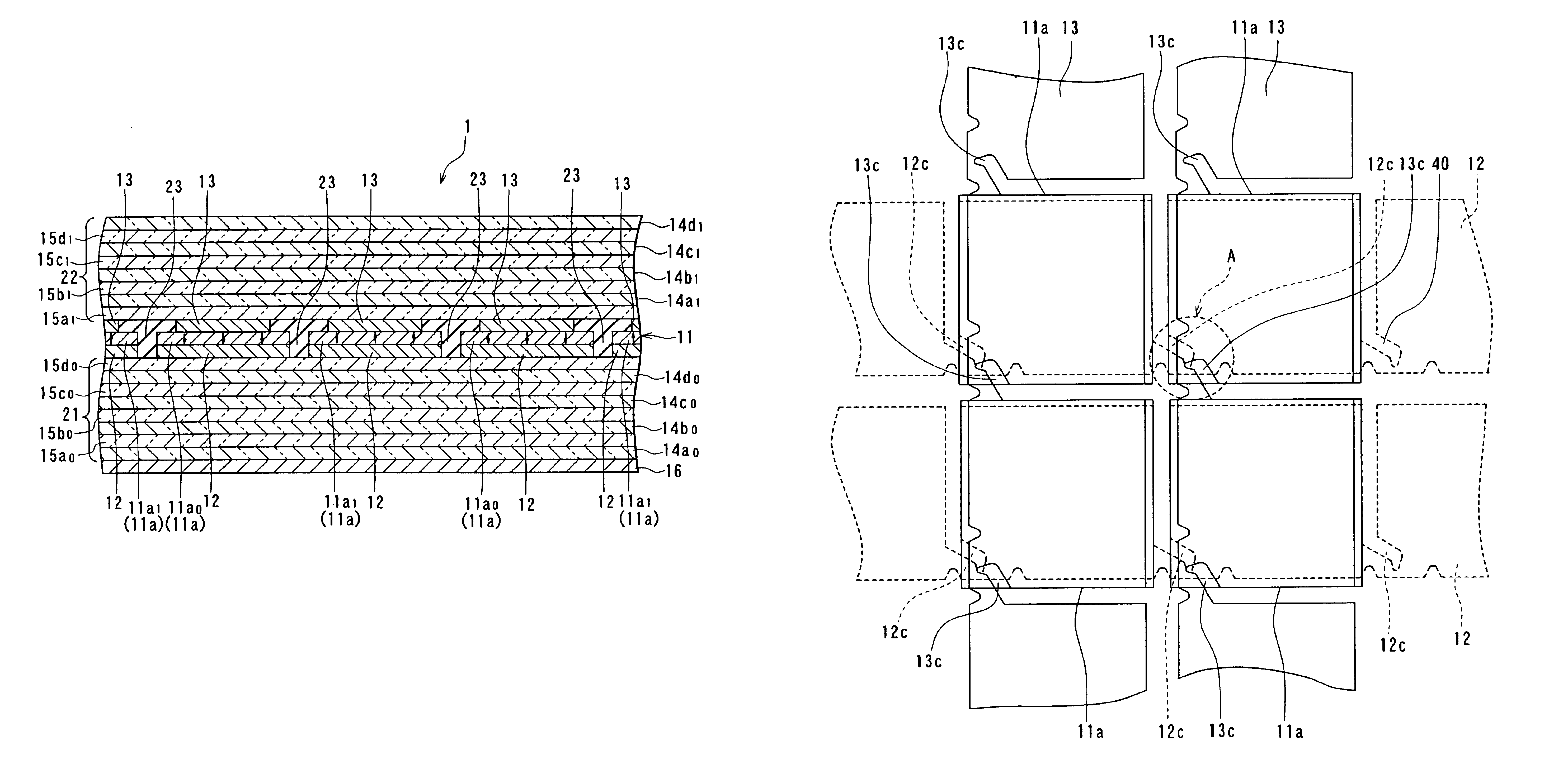
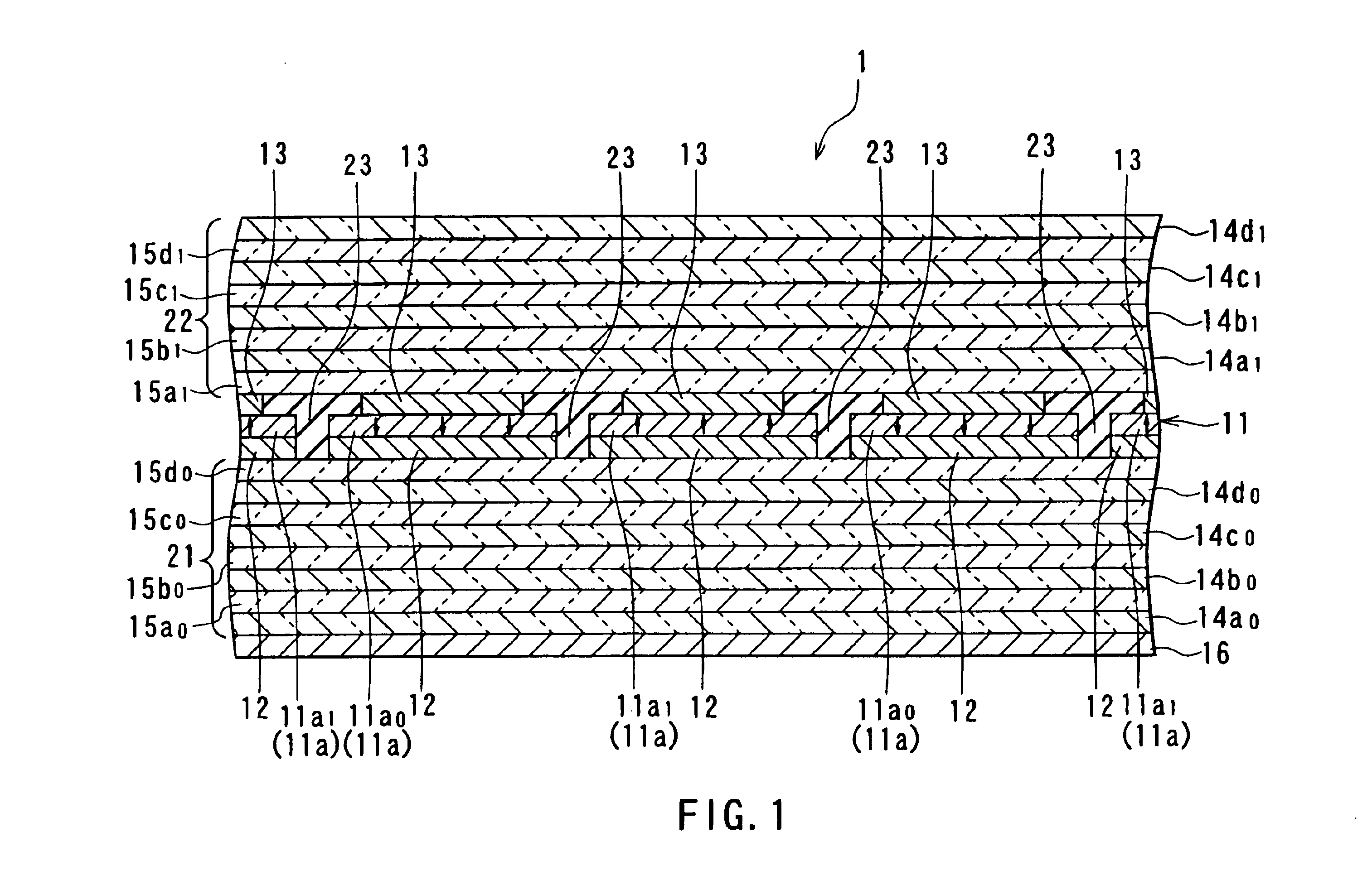
First, a spatial light modulator according to a first embodiment of the invention will be described. FIG. 1 is a sectional view showing the essential portion of the spatial light modulator of this embodiment.

As shown in FIG. 1, the spatial light modulator 1 of this embodiment includes: a magnetic layer 11 made of a magneto-optic material; a plurality of lower conductor layers 12 adjacent to the bottom surface of the magnetic layer 11; and a plurality of upper conductor layers 13 adjacent to the top surface of the magnetic layer 11. Thus, the lower conductor layers 12 and the upper conductor layers 13 are placed to sandwich the magnetic layer 11. The lower conductor layers 12 correspond to the first conductor layers of the invention, and the upper conductor layers 13 correspond to the second conductor layers of the invention.

The magnetic layer 11 includes a plurality of pixels 11a in each of which a magnetization direction is independently set and each of which has ...

second embodiment

[Second Embodiment]

A spatial light modulator according to a second embodiment of the invention will now be described. FIG. 14 is an explanatory view showing a schematic configuration of the spatial light modulator of this embodiment. As shown in FIG. 14, the spatial light modulator61 of this embodiment includes an optical rotatory layer 63 provided to be adjacent to the top surface of the upper dielectric layer portion 22, in addition to the components of the spatial light modulator 1 of the first embodiment. The optical rotatory layer 63 includes a layer formed of a magneto-optic material. The optical rotatory layer 63 may be made of a one-dimensional magnetophotonic crystal.

The whole magnetization in the optical rotatory layer 63 is set to have the same direction, for example, an upward direction in FIG. 14. The optical rotatory layer 63 rotates the polarization direction of passing light by a predetermined angle by the magneto-optic effect (Faraday effect).

The remainder of the co...


PUM

PropertyMeasurementUnit
transmittanceaaaaaaaaaa
thicknessaaaaaaaaaa
widthaaaaaaaaaa

Abstract

A spatial light modulator includes: a magnetic layer that is made of a magneto-optic material and includes a plurality of pixels in each of which a magnetization direction is independently set and each of which has a function of causing a rotation of a polarization direction of incident light depending on the magnetization direction by a magneto-optic effect; a plurality of first conductor layers and a plurality of second conductor layers arranged to intersect with each other at positions corresponding to the individual pixels, through which currents for generating magnetic fields to set the magnetization directions in the individual pixels are passed; and a plurality of dielectric layers for enhancing the function of the pixels. A polarization direction of light incident on the spatial light modulator is rotated depending on the magnetization direction of each pixel.

Description

BACKGROUND OF THE INVENTION1. Field of the InventionThe present invention relates to a spatial light modulator for spatially modulating incident light.2. Description of the Related ArtA spatial light modulator for spatially modulating incident light is used in the field of an optical information processing, a computer-generated hologram or the like.A conventional spatial light modulator includes one using a liquid crystal and one using a micro-mirror device.In the foregoing field of the optical information processing, the computer-generated hologram or the like, since a large amount of information must be processed at high speed, it is desirable that the spatial light modulator has a high operation speed.However, the spatial light modulator using a liquid crystal has a problem that the operation speed is low. For example, even in the spatial light modulator using a ferroelectric liquid crystal that has a high operation speed among liquid crystals, the response time is of the order o...

Claims


Application Information

Patent Timeline
Patent Type & Authority Patents(United States)
IPC IPC(8): G02F1/09G02F1/01
CPCG02F1/09G02F1/091G03H2240/15G03H2225/20G02F2203/12
Inventor INOUE, MITSUTERUCHO, JAE-KYONG
Owner OPTWARE
Why Eureka
Try Eureka