Bearing system for high-speed rotating machinery

a bearing system and high-speed rotating technology, applied in the direction of elastic bearings, rigid support of bearing units, machines/engines, etc., can solve the problems of substantial total friction loss of the complete bearing system, inability to achieve sufficient durability, and early attempts to use ball bearings. failure, etc., to achieve high efficiency, high reliability, and high efficiency.

Inactive Publication Date: 2005-04-12
WOLLENWEBER WILLIAM E
View PDF13 Cites 55 Cited by
  • Summary
  • Abstract
  • Description
  • Claims
  • Application Information

AI Technical Summary

Benefits of technology

The bearing system of this invention provides a reliable, stable, shock and vibration-resistant, highly efficient system that is insertable in the stationary housing as an assembly, thus permitting inexpensive manufacture and ease of replacement in the machines in which it is used.

Problems solved by technology

Early attempts to use ball bearings were unsuccessful in that sufficient durability could not be achieved.
However, the high rotational speed of the collar attached to the shaft resulted in a high thrust frictional loss which, in addition to the frictional losses of the sleeve bearings, resulted in a substantial total frictional loss for the complete bearing system.
In this bearing system, however, the differential speed between the sleeve bearing and rotor is the very high rotative speed of the rotor.
Since sleeve bearing frictional losses are proportional to the square of the differential rotating speed, this system has an inherent higher frictional loss than a full-floating sleeve bearing system.
The residual imbalance in the rotor forces the non-rotating cylinder to move orbitally, causing the mating surfaces to be subject to fretting.
Thus a solid film lubricant must be placed between the mating surfaces to mitigate the fretting problem; however, this problem remains an inherent disadvantage with this type of non-rotating cylinder system and contributes to a limited service life in the field.

Method used


Image

  • Bearing system for high-speed rotating machinery
  • Bearing system for high-speed rotating machinery

Examples


Embodiment Construction

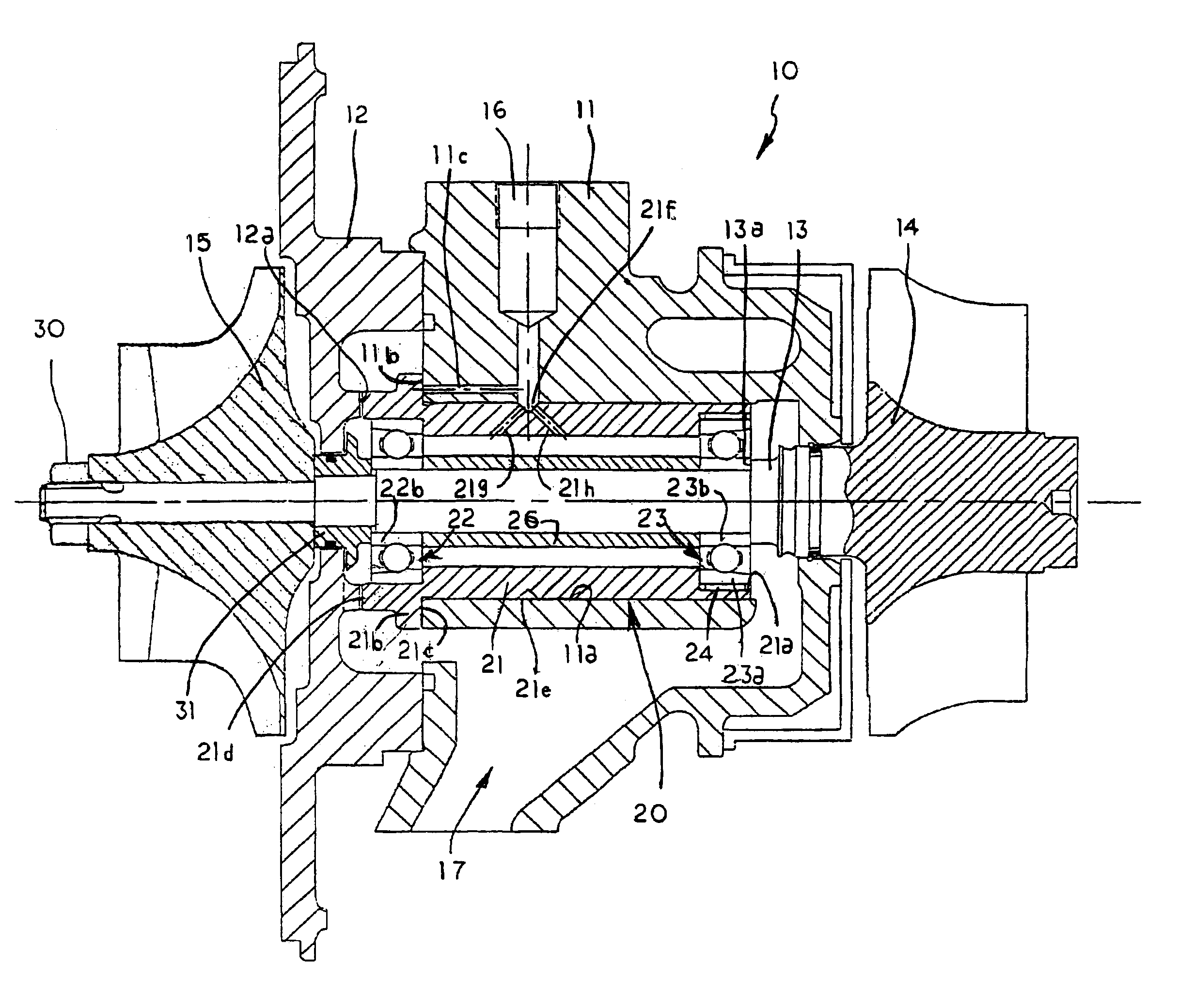
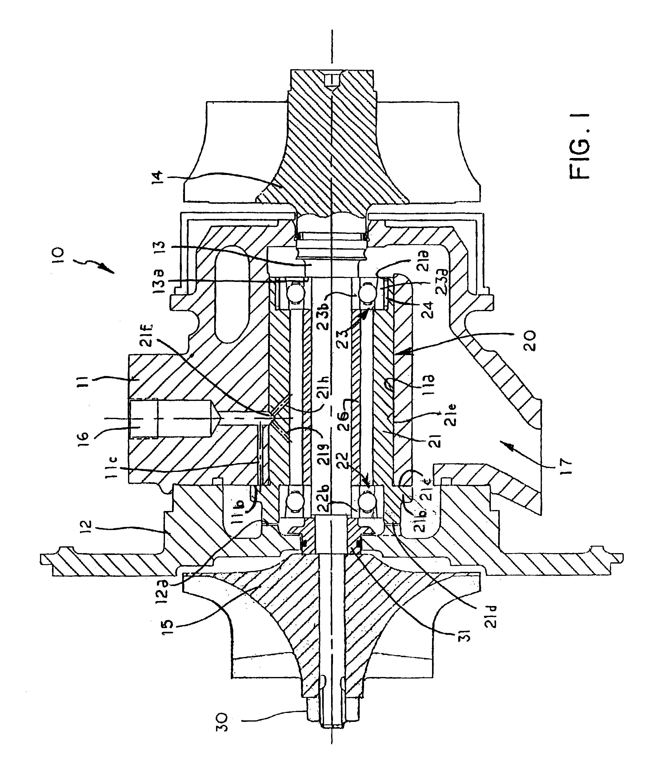
The bearing system of this invention is adapted to support, within stationary elements of a machine, a high-speed rotating shaft.

In a turbocharger 10, for example, stationary elements of the turbocharger, that is, the bearing housing 11 and end housing 12 encloses a rotating shaft 13 carrying a turbine wheel 14 at one end and a compressor wheel 15 at the other end. The bearing system 20 of the invention carries the rotating shaft 13 and is carried by the bearing housing 11. As well known in the art, the shafts of turbochargers have rotating speeds of 60,000 to 200,000 rpm and are exposed to the very high temperatures of engine exhaust gases at their turbine ends.

The bearing system 20 of this invention comprises an elongated rotatable cylinder 21 with one angular contact ball bearing 22 at its compressor end and another angular contact ball bear 23 at its turbine end. Angular contact ball bearings, as known in the art, are adapted to resist thrust in one axial direction, but not the ...


PUM


Abstract

A bearing system for a turbocharger shaft includes two angular contact ball bearings mounted in the opposite ends of a lubricated rotatable elongated cylinder, which includes a radially extending flange at one end that cooperates with stationary housing portions and carries the thrust load of the rotor in both directions. The angular contact ball bearing on the turbine end (hot end) of the machine is provided with a radial spring between the outside of its outer race and the elongated cylinder, which prevents rotation of the outer race, but still allows axial movement of the outer race in the elongated cylinder due to axial expansion of the shaft when exposed to high temperature. The inner races of the ball bearings are separated by a spacer, which is clamped in place between the bearings when the rotor assembly lock nut is tightened. Thus, the inner race of the bearings and spacer rotate with the shaft as part of the rotating assembly.

Description

FIELD OF THE INVENTIONThis invention relates to bearing systems for machinery with shafts that rotate at high speeds and are exposed at one end to high temperatures, such as turbochargers used on internal combustion engines.BACKGROUND OF THE INVENTIONTurbochargers for internal combustion engines have been widely used on both diesel and gasoline engines for many years. A great deal of effort was expended in the early years of turbocharger development to produce a bearing system that exhibited sufficient durability to make a small size turbocharger commercially viable. Early attempts to use ball bearings were unsuccessful in that sufficient durability could not be achieved. Furthermore, bearing systems for small turbochargers must be capable of mass production manufacturing methods, be low in cost, and easily serviced in the field.Research and development tests during the 1960's resulted in the perfection of floating sleeve-bearing systems that were capable of suppressing the problems...

Claims


Application Information

Patent Timeline
Patent Type & Authority Patents(United States)
IPC IPC(8): F01D25/16F16C27/04F16C35/04F16C35/06F16C35/077F16C27/00F16C19/52F16C19/00F16C19/54
CPCF01D25/164F16C19/52F16C27/04F16C35/061F16C21/00F16C19/548F16C35/077F16C2360/24Y10S384/901F16C17/04F16C19/163
Inventor WOLLENWEBER, WILLIAM E.
Owner WOLLENWEBER WILLIAM E
Why Eureka
Try Eureka