Ion and charged particle source for production of thin films

Inactive Publication Date: 2005-04-12
WILLOUGHBY ROSS CLARK +2
View PDF3 Cites 84 Cited by
  • Summary
  • Abstract
  • Description
  • Claims
  • Application Information

AI Technical Summary

Benefits of technology

The physical separation of the ion or charge particle source region from the deep potential-well focusing region by a high transmission element (HTE) solves many of the efficiency problems associated with conventional approaches to ion collection at atmospheric pressure. With the present invention, dispersed ions can be focused to a small diame

Problems solved by technology

The application of organic, inorganic, biomolecular thin films using vacuum based processes is a common practice, however, atmospheric processes for thin film deposition have been of limited practice (2).
The requirement of each of these steps to be performed under vacuum creates substantial cost and complexity.
As a consequence of a wide variety of dispersive processes, efficient sampling of ions from atmospheric pressure sources to small cross-sectional targets or through small cross-sectional apertures and tubes (usually less than 1 mm) into a targeted small region in space becomes quite problematic.
This general approach in severely restricted by the need for precise aperture alignment and source positioning and very poor sampling efficiency.
This approach to focusing ions from atmospheric sources is limited by the acceptance angle of the field generated by the cone.
As with planar apertures, source positioning relative to the aperture is critical to performance and collection efficiency is quite low.
This configuration has a clear disadvantage in that the potential well resulting from the field penetration is dependent of ion source position, or potential.
High volta

Method used


Image

  • Ion and charged particle source for production of thin films
  • Ion and charged particle source for production of thin films
  • Ion and charged particle source for production of thin films

Examples


Embodiment Construction

—GENERAL

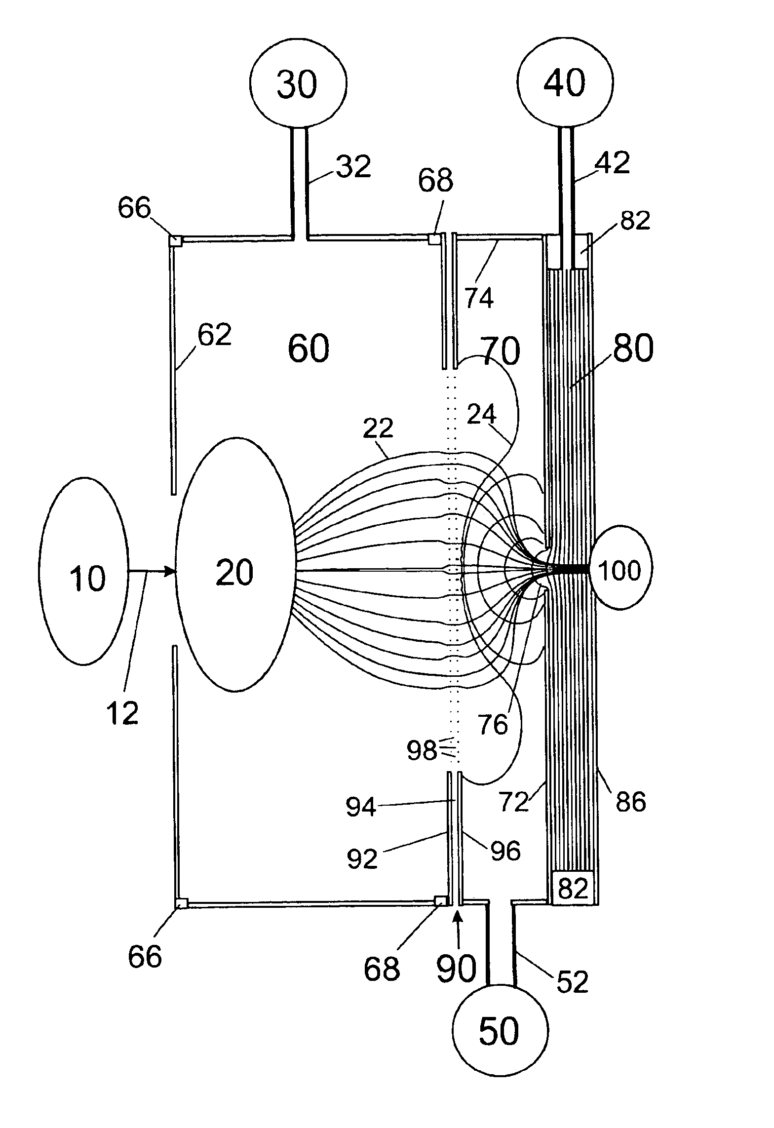
The present invention describes a variety of electro-optical devices and the associated methods of delivering materials to a target surface with precise control over position, composition, and time of deposition. The invention is constructed as to provide both a continuous, or discontinuous supply of ions or charged particles for deposition in desired patterns onto target surfaces. The lens elements may be constructed of predetermined mask patterns of composite construction in 3-dimensional conformations to yield maximum ion directing efficiency and fine directed beam resolution for fine resolution patterning of materials. Alternately, the lens may be a simple, non-conformal 2-dimensional or 3-dimensional shadow mask that imparts its pattern upon the directed, collimated ion beam to yield a structured pattern of deposits toward the substrate. Lastly, the ion stream may be controlled by a lens element array (2-dimensional or 3-dimensional conformal architecture) constructed f...


PUM


Abstract

The present invention includes a delivery means of material to be deposited onto thin film surfaces with precise spatial, temporal, compositional, and energy resolution for controlled reactions, patterning (2-dimensional and 3-dimensional), and removal of materials or reaction products of materials from thin film surfaces. The device includes a near atmospheric pressure means of generating ions, ion clusters, or charged particles as a material form to deliver said materials onto substrate surfaces. The device relies on shaped, patterned, conformal ion lenses, and individually addressable lens elements of a lens arrays to create an integrated deposition system for printed patterns of thin films. The devices and methods provide a novel approach to delivering materials to a surface, removing materials from a surface, or creating new materials at or on the surface. These methods and devices may be used in applications of thin film deposition, micro-electronics and semi-conductor manufacturing, printing, surface interfacial layers, coating, painting, sample and reagent treatment, preparation for sensors, chemical analysis, and fabricating 2- and 3-dimensional structures and devices.

Description

SEQUENCE LISTING OR PROGEMNot Applicable.BACKGROUND OF THE INVENTION1. Field of the InventionThe present invention relates to devices and methods to deliver thin film materials onto substrates using near atmospheric pressure (or alternatively above atmospheric pressure) generated ions, ion clusters, or charged particles (droplets and / or solid particles) as the material form, or as a precursor to reaction products that are the material form. The technique relies on the use of ion and particle generators in combination with shaped, patterned, conformal ion lenses and individually addressable elements of a lens array to create an integrated deposition system for printed patterns of thin films. The devices and methods provide a novel approach to delivering materials to a surface, removing materials from a surface, or creating new materials at or on the surface. Transport of material to and away from the surface is precisely controlled spatially, temporally, and compositionally. These me...

Claims


Application Information

Patent Timeline
IPC IPC(8): H01J49/10H01J37/00H01J37/30H01J37/301H01J37/317
CPCB82Y10/00B82Y40/00H01J37/3007H01J37/301H01J37/3174H01J37/3175H01J37/3178H01J2237/31776H01J2237/08H01J2237/164H01J2237/303H01J2237/31732H01J2237/3174H01J49/10
Inventor WILLOUGHBY, ROSS CLARKSHEEHAN, EDWARD WILLIAMFRIES, CAROLYN A
Owner WILLOUGHBY ROSS CLARK
Why Eureka
Try Eureka