
Indirectly heated button cathode for an ion source

a technology of ion source and button cathode, which is applied in the direction of discharge tube main electrode, ion beam tube, instruments, etc., can solve the problems of reducing the life of consumable elements within the ion source, especially the cathode, and achieve the effect of increasing the energy density of the plasma

Inactive Publication Date: 2005-04-12
APPLIED MATERIALS INC
View PDF11 Cites 11 Cited by
  • Summary
  • Abstract
  • Description
  • Claims
  • Application Information

AI Technical Summary

Benefits of technology

It is an object of the present invention to provide an improved cathode structure for the ion source of an ion implanter to enable the ion source to be optimised for the production of multiple charge state ions with a satisfactory cathode life time.
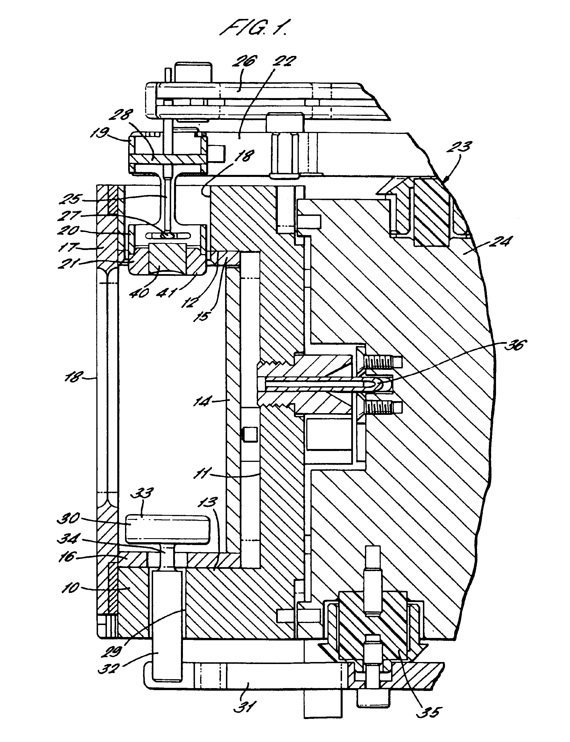
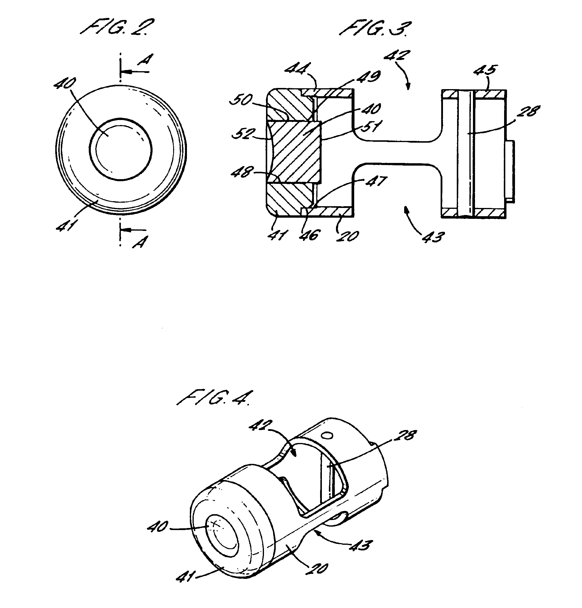
Because of the thermal barrier between the central slug piece of the button member and the collar piece, the thermal mass to be heated is reduced and the central portion of the front face of the button member can be heated to a higher temperature to increase thermionic emission. The electron emission area of the cathode can therefore be reduced in size, resulting in a more concentrated plasma within the arc chamber. The more concentrated plasma tends to have a higher energy density resulting in more favourable production of ions at higher charge states. Both the slug piece and the collar piece of the button member may be of tungsten and can be made thicker to maximise cathode life.
Also, the front face of the slug piece, forming the central portion of the thermionic electron emitting face of the button member, may be made concave. This produces a slight focus of the primary electrons emitted from the front face, so as further to increase the energy density of the plasma.
The modified button cathode can be used to replace prior art button cathodes, typically having a solid tungsten button member, with minimum additional modification of the ion source.

Problems solved by technology

However this usually involves operating the ion source with a more intense arc, so that the life of consumable elements within the ion source, particularly the cathode, is reduced.

Method used


Image

  • Indirectly heated button cathode for an ion source
  • Indirectly heated button cathode for an ion source
  • Indirectly heated button cathode for an ion source

Examples


Embodiment Construction

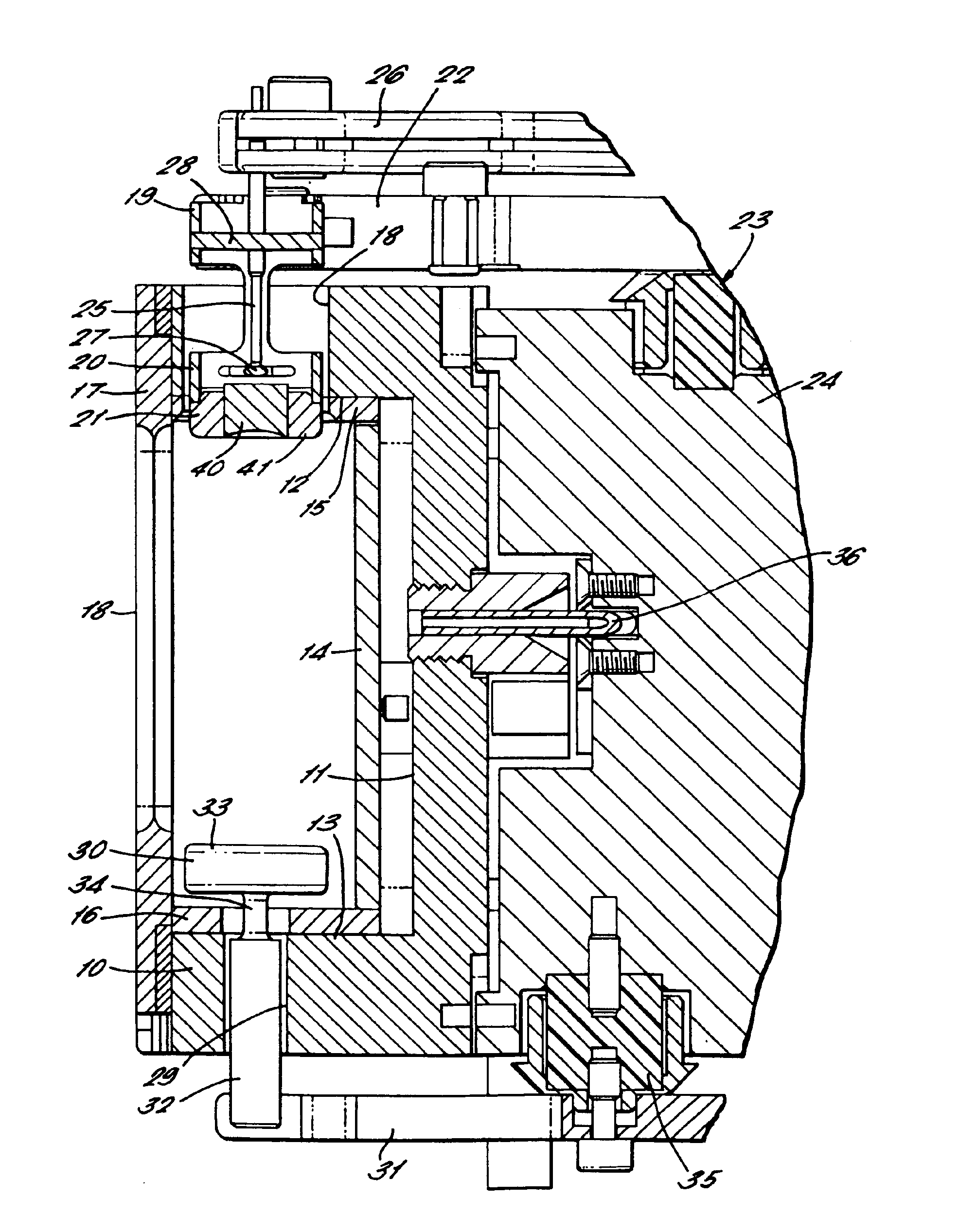
In the description and claims that follow, relative terms such as upper and lower, rear and front have been used for simplicity of description. Upper and lower have been used only with reference to the orientation of the example illustrated in FIG. 1 of the drawings, and, in an actual installation of the embodiment, any orientation relative to vertical is feasible. Rear and front have been used such that the distinction should be apparent from the context. For example, the terms are used with reference to the arc chamber in accordance with the convention that the ion beam is emitted from the front. Similarly, the term front is used with reference to the face of the button member of the cathode to denote the face which is directed away from the neighbouring arc chamber wall and into the interior of the arc chamber.

In FIG. 1, the arc chamber of an ion source comprises an arc chamber body 10 having a rear wall 11 and upper and lower end walls 12 and 13. The rear wall 11 and upper and l...


PUM


Abstract

An indirectly heated button cathode for use in the ion source of an ion implanter has a button member formed of a slug piece mounted in a collar piece. The slug piece is thermally insulated from the collar piece to enable it to operate at a higher temperature so that electron emission is enhanced and concentrated over the surface of the slug piece. The slug piece and collar piece can be both of tungsten. Instead the slug piece may be of tantalum to provide a lower thermionic work function. The resultant concentrated plasma in the ion source is effective to enhance the production of higher charge state ions, particularly P+++ for subsequent acceleration for high energy implantation.

Description

FIELD OF THE INVENTIONThis invention relates to an indirectly heated button cathode for an ion source, in particular for use in an ion implanter for implanting ions into target substrates such as semiconductor wafers.BACKGROUND OF THE INVENTIONIt is known to use indirectly heated cathodes in the arc chambers of ion sources. In such arrangements, the cathode is formed as a button having a front thermionic electron emitting surface and a rear surface. The button is typically heated by electron impact on the rear surface, by electrons emitted and accelerated from a filament located behind the rear surface of the cathode button. With this construction, the filament is protected from sputtering by energetic particles in the arc plasma formed in the arc chamber of the ion source. The heated cathode button emits thermionic electrons at its front surface, and these are accelerated by the arc potential in the arc chamber, to initiate and maintain the required arc. The cathode button can be m...

Claims


Application Information

Patent Timeline
IPC IPC(8): H01J37/08H01J27/00
CPCH01J1/20H01J1/26H01J27/08H01J37/3171H01J37/08H01J2237/082H01J2237/061
Inventor FARLEY, MARVINSAKASE, TAKAOSATOH, SHURYDING, GEOFFREYROSE, PETERCHRISTOU, CHRISTOS
Owner APPLIED MATERIALS INC
Learn More