
Laser thermal transfer recording method and apparatus therefor

a technology of thermal transfer and recording method, applied in thermography, duplicating/marking methods, instruments, etc., can solve the problems of inability to achieve satisfactorily high resolution, inability to ensure sharp outline of laser fusion system (3), lack of sharp dots in recording dots, etc., to achieve excellent print-matching performance, high stability, and high definition

Inactive Publication Date: 2005-04-12
FUJIFILM HLDG CORP +1
View PDF33 Cites 8 Cited by
  • Summary
  • Abstract
  • Description
  • Claims
  • Application Information

AI Technical Summary

Benefits of technology

The present invention aims to solve the problems of hitherto used materials in the field of thermal transfer printing by providing large-sized DDCP with high definition, high stability, and excellent print-matching performance. Additionally, the invention provides an image-receiving sheet that can consistently and reliably receive the image forming layer of a laser-energy thermal transfer sheet, and the transfer is achieved even under different temperature-humidity conditions. The invention also provides a method for forming multicolored images of high quality and consistent transfer density on image-receiving sheets.

Problems solved by technology

However, all of these systems have a problem that the shape of recorded dots lacks in sharpness.
More specifically, the laser sublimation system (1) uses dyes as coloring materials, and so the degree of similarity to prints is insufficient, the dots formed have blurred outlines since sublimation of coloring materials is utilized therein, and satisfactorily high resolution cannot be achieved.
In addition, the laser fusion system (3) cannot ensure sharp outlines because of fluidity of fused matter.
Although hitherto used materials permit automatic stacking of several sheets, they cause a considerable frequency of troubles, including sticking, waving, curling or / and jutting troubles, when it is required to automatically stack, e.g., 20 image sheets by all-night automatic operation.
Therefore, the monitoring by an operator is required, and so the automatic operation is virtually impossible as matters stand.

Method used


Image

  • Laser thermal transfer recording method and apparatus therefor
  • Laser thermal transfer recording method and apparatus therefor
  • Laser thermal transfer recording method and apparatus therefor

Examples


example 1-1

Preparation of Thermal Transfer Sheet K (Black)

[Formation of Backing Layer]

(Preparation of Coating Composition for First Backing Layer)

Aqueous dispersion of acrylic resin  2 parts(Jurimer ET410, 20 wt %, produced by Nippon Junyaku Co.,Ltd.)Antistatic agent7.0 parts(aqueous dispersion of tin oxide-antimony oxidemixture, average grain size: 0.1 μm, 17 wt %)Polyoxyethylene phenyl ether0.1 partsMelamine compound0.3 parts(Sumitex Resin M-3, produced by Sumitomo Chemical Co.,Ltd.)Distilled water to make 100 parts 

(Formation of First Backing Layer)

One surface (back surface) of a 75 μm-thick biaxially stretched polyethylene terephthalate film (Ra of both surfaces: 0.01 μm) as a substrate was subjected to corona treatment, coated with the coating composition for a fist backing layer so as to have a dry thickness of 0.03 μm, and then dried for 30 seconds at 180° C. Thus, the first backing layer was formed. The substrate used herein had Young's modulus of 450 kg / mm2 (approximately 4.4 GPa) in ...

example 1-2

Transfer images were formed in the same manner as in Example 1-1, except that an image-receiving sheet using a 100 μm-thick white PET support (Lumiler #100E20, produced by Toray Industries, Inc.) was used in place of the image-receiving sheet used in Example 1-1.

example 2-1

Preparation of Thermal Transfer Sheet K (Black)

[Formation of Backing Layer]

(Preparation of Coating Composition for First Backing Layer)

Aqueous dispersion of acrylic resin  2 parts(Jurimer ET410, 20 wt % on solid basis, produced by NipponJunyaku Co., Ltd.)Antistatic agent7.0 parts(aqueous dispersion of tin oxide-antimony oxide mixture,average grain size: 0.1 μm, 17 wt %)Polyoxyethylene phenyl ether0.1 partsMelamine compound0.3 parts(Sumitics Resin M-3, produced by Sumitomo Chemical Co.,Ltd.)Distilled water to make 100 parts 

(Formation of First Blacking Layer)

One surface (back surface) of a 75 μm-thick biaxially stretched polyethylene terephthalate film (Ra of both surfaces: 0.01 μm) as a substrate was subjected to corona treatment, coated with the coating composition for a fist backing layer so as to have a dry thickness of 0.03 μm, and then dried for 30 seconds at 180° C. Thus, the first backing layer was formed. The substrate used herein had Young's modulus of 450 kg / mm2 (approxima...


PUM

PropertyMeasurementUnit
thicknessaaaaaaaaaa
pressureaaaaaaaaaa
surface roughnessaaaaaaaaaa

Abstract

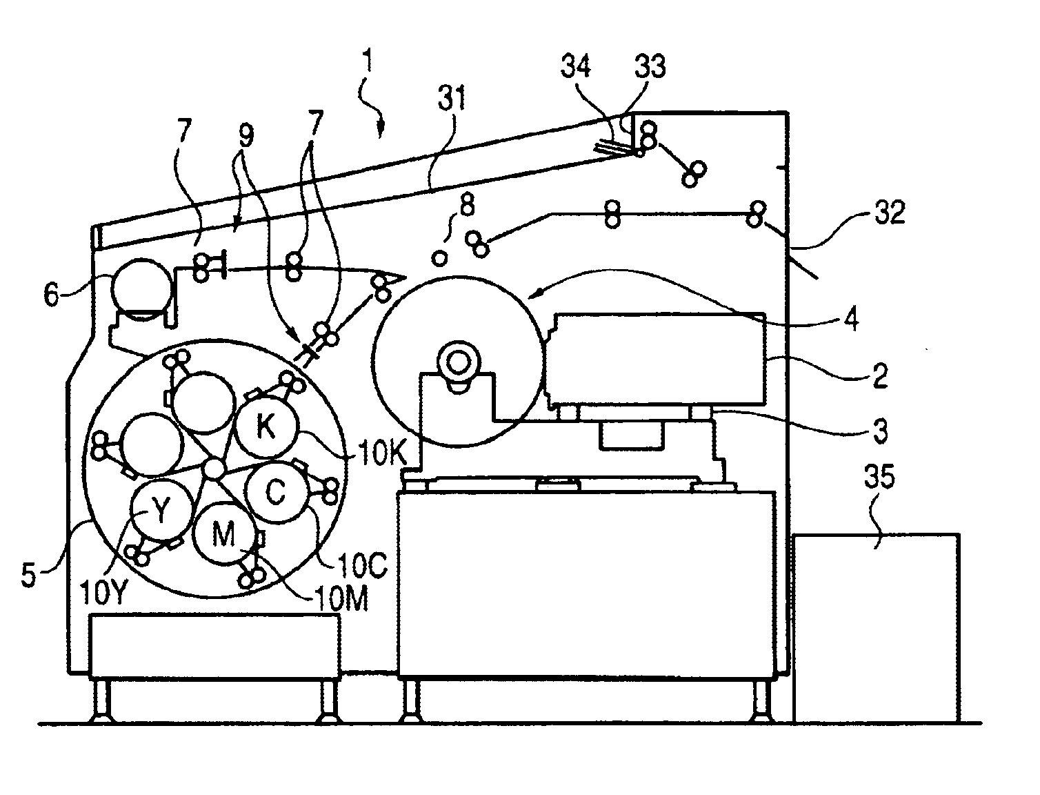
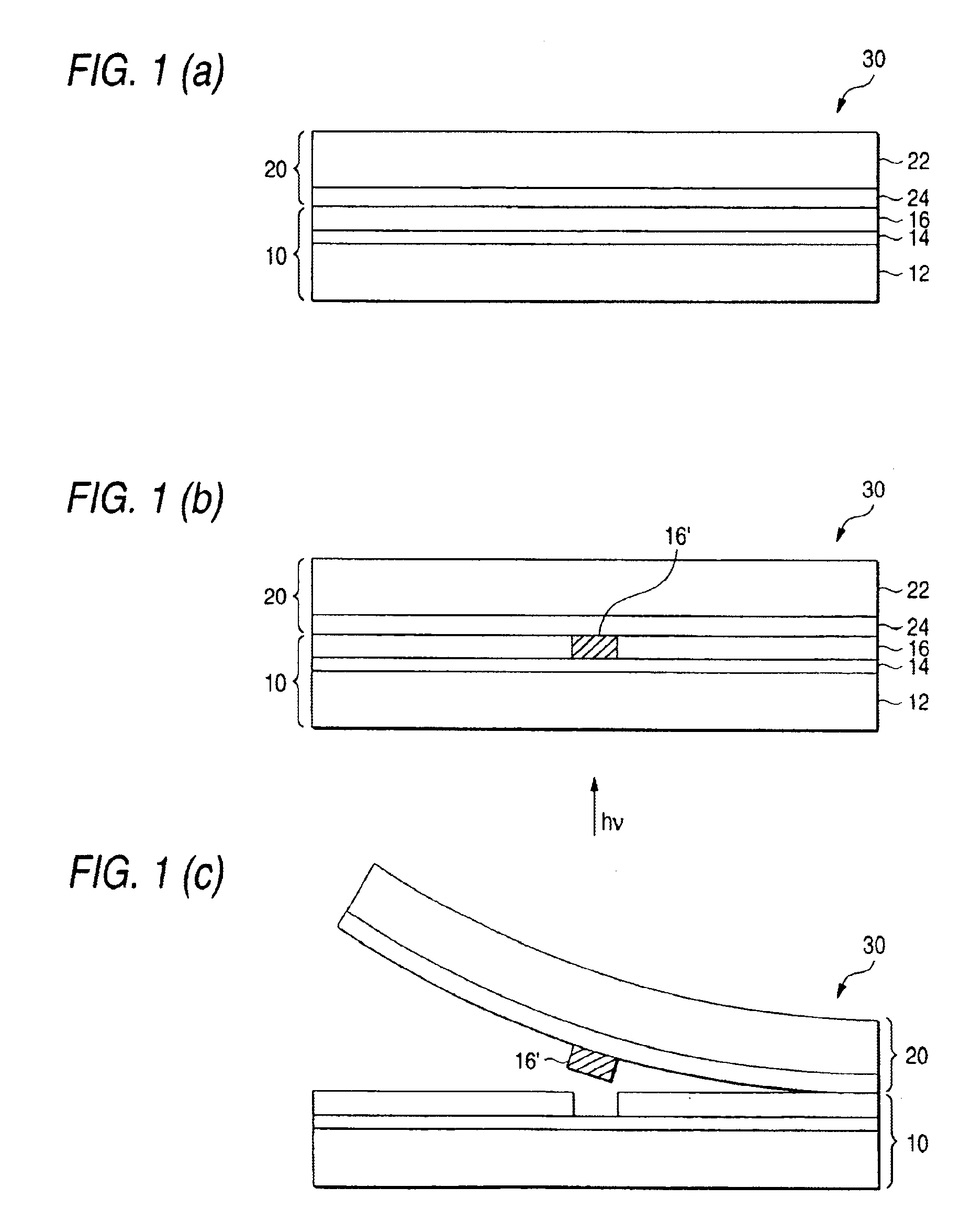
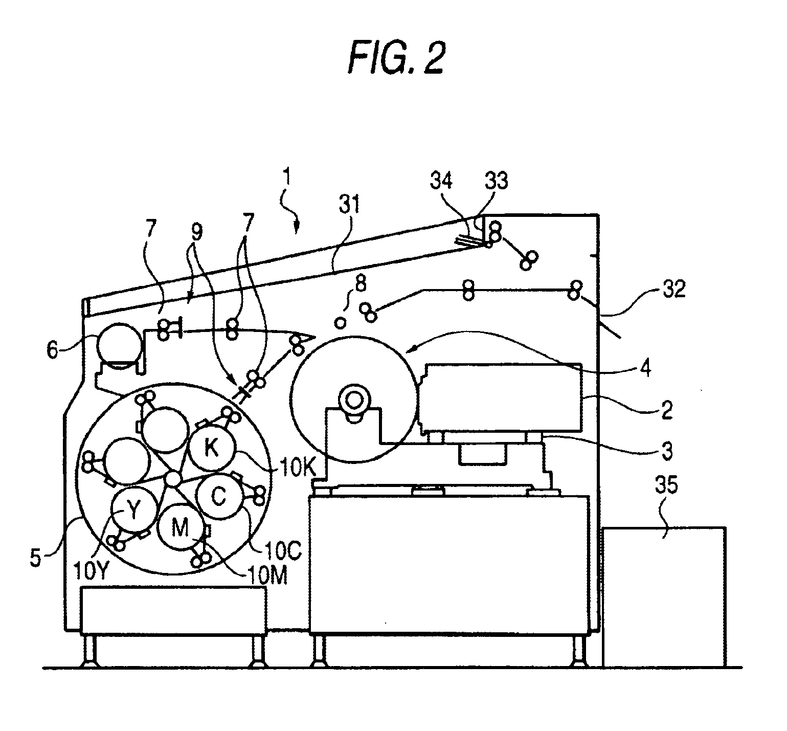
A laser thermal transfer recording method comprises: dispensing a thermal transfer sheet and an image-receiving sheet to an exposure recording device; cutting each of the sheets into pieces of a predetermined length; superposing each of the cut pieces of the image-receiving sheet on each of the cut pieces of the thermal transfer sheet; loading an exposure drum installed in the exposure recording device with the thus superposed pieces of sheets; and irradiating the sheets loaded on the exposure drum with a laser beam according to image information, in which the laser beam is absorbed in the thermal transfer sheet and converted into a heat, and an image is transferred onto the image-receiving sheet by the heat converted from the laser beam, wherein each surface of the thermal transfer sheet and the image-receiving sheet is cleaned by contacting with an adhesive roller that includes an adhesive material on its surface, in which the adhesive roller is disposed in any one of a feeding part and a conveying part of the thermal transfer sheet and the image-receiving sheet in the exposure recording device, and the image-receiving sheet has a thickness of 110 to 160 μm, and at least one of pieces of the thermal transfer sheet and pieces of the image-receiving sheet is stacked while be blown.

Description

FIELD OF THE INVENTIONThe present invention relates to a method of forming multicolored images and apparatus therefor wherein are used multicolor image-forming materials that can form high-resolution, full-color images when exposed to laser light. In particular, the invention is concerned with a multicolored image formation method and apparatus therefor wherein are used multicolor image-forming materials useful for producing color proofs in the field of graphic arts (DDCP: Direct Digital Color Proofs) or masking images from digital image signals through the use of laser recording technique.BACKGROUND OF THE INVENTIONIn the field of graphic arts, printing of a printing plate is carried out using a set of color separation films produced from a color original with the aid of lithographic films. Prior to going into real printing (practical printing operation), color proofs are generally produced from color separation films in order to check up on errors in the step of color separation a...

Claims


Application Information

Patent Timeline
Patent Type & Authority Patents(United States)
IPC IPC(8): B41J2/475B41M5/40B41J2/315B41J2/48B41M5/382B41M5/42B41M5/46B41M7/00
CPCB41J2/4753B41M5/38207B41M5/38214B41M5/46B41M5/42B41M5/426B41M5/38221
Inventor SUGIYAMA, SUSUMUSHIMOMURA, AKIHIRO
Owner FUJIFILM HLDG CORP
Learn More