Apparatus and method for coating pipes

a technology of apparatus and coating pipes, applied in the direction of liquid/solution decomposition chemical coating, solid/suspension decomposition chemical coating, etc., can solve the problems of difficult for operatives to apply an even coating all around the surface of the pipe, toxic coatings, etc., and achieve the effect of reducing time and energy costs

Inactive Publication Date: 2005-04-19
PIPELINE INDUCTION HEAT
View PDF9 Cites 64 Cited by
  • Summary
  • Abstract
  • Description
  • Claims
  • Application Information

AI Technical Summary

Benefits of technology

[0012]The apparatus and method enable a coating to be applied completely around the periphery of a pipe using only one spray gun, whilst the body of the apparatus remains rotationally fixed relative to the axis of the pipe. This provides for relatively simple apparatus and minimises the amount of waste produced when flushing the spray gun. It also means that there need only be one point where the coating overlaps, reducing the risk of the coating sagging or running.
[0032]Preferably the coating is a polyurethane product. Polyurethane normally sets in approximately 3 seconds which is too fast to allow it to be sprayed because it would set in the nozzle, thereby one of the components of the two part system is preferably a catalyst which slows the setting time to between 10 seconds to 4 minutes depending on the speed required for a particular application. Polyurethane is not normally used in subsea applications because it is more costly than the usually used polyolefin. Also the usual method of application, injection into a mould, requires a considerable quantity of this product. However by being able to apply by spraying in an enclosed environment a thinner coating is applied, making it more cost effective to use. Polyurethane has particularly good properties for use in an environmentally unfriendly application, such as subsea. Also it is able to adhere better to a large number of factory applied coatings for example FBE (Fusion bonded epoxy) polyolefin, polypropylene, polyethylene, polyurethane, concrete and others.

Problems solved by technology

This is time consuming.
Several operatives are required to achieve this, which is costly.
It is difficult for operatives to apply an even coating all around the surface of a pipe, especially when under considerable time pressure.
This is undesirable.
The coatings used are often toxic and present an environmental hazard.
With manual spraying it is found that a significant fraction of the coating used enters the environment as overspray and through flushing the spraying apparatus.
As this machine is for line coating of pipe it is generally unsuitable for coating girth welds on site and also has a number of other drawbacks.
In particular it is rather cumbersome and would therefore be difficult to rapidly mount and dismount on a pipe, as required when coating welds on site.
The materials used to coat field welds often cause blockages within spray guns.
With two spray guns the risk of a blockage occurring is double that of a single gun.
This is inconvenient and / or expensive.
This is also inconvenient and increases losses due to overspray.
Having two guns also means that there are two points at which the coating applied to a pipe will overlap increasing the risk that the coating will run or sag.
Two guns also increases wastage of coating when the spraying equipment is flushed.
This is undesirable.
Indeed, in some countries contemporary environmental concerns are such that such operations would be forbidden.

Method used


Image

  • Apparatus and method for coating pipes
  • Apparatus and method for coating pipes
  • Apparatus and method for coating pipes

Examples


Embodiment Construction

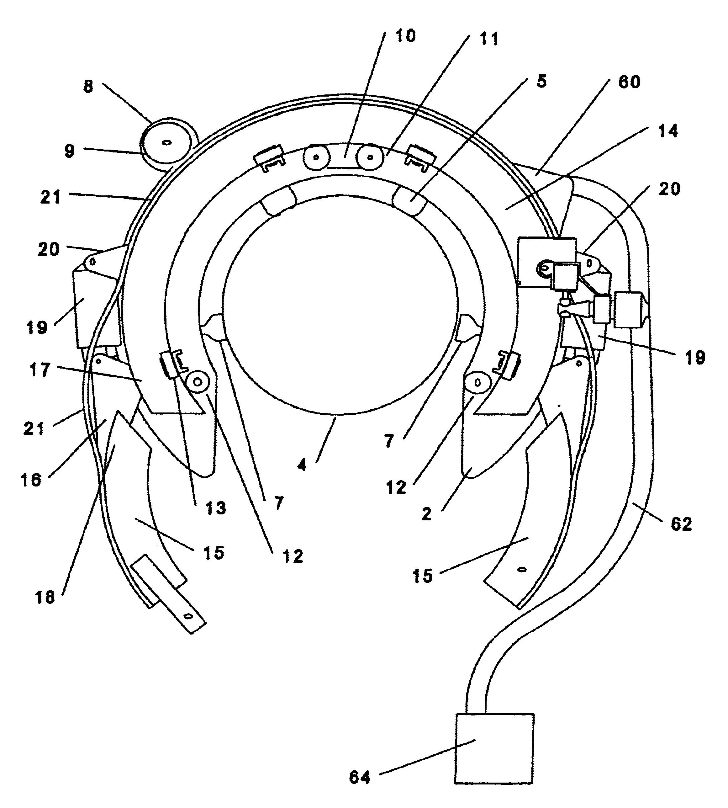
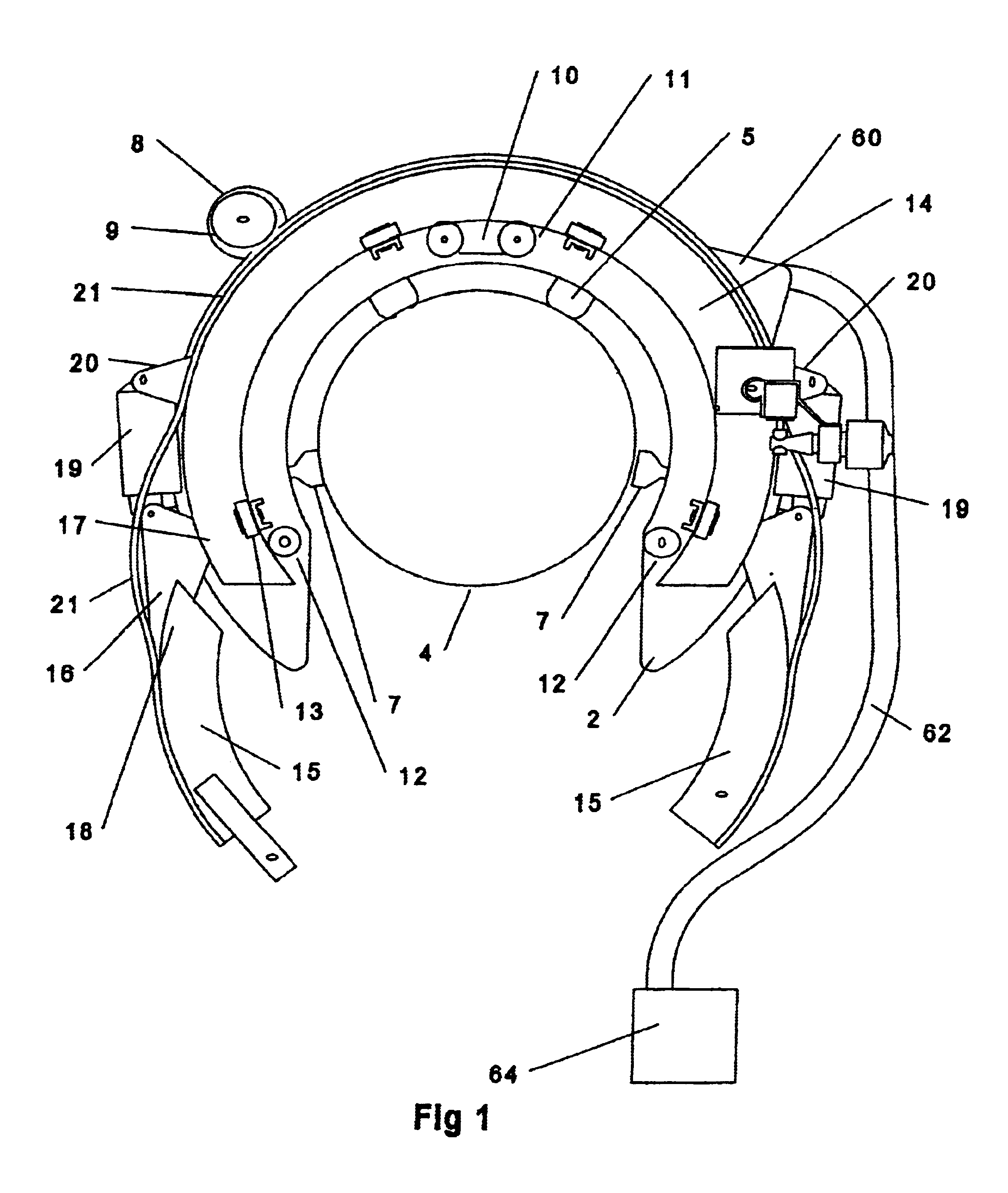
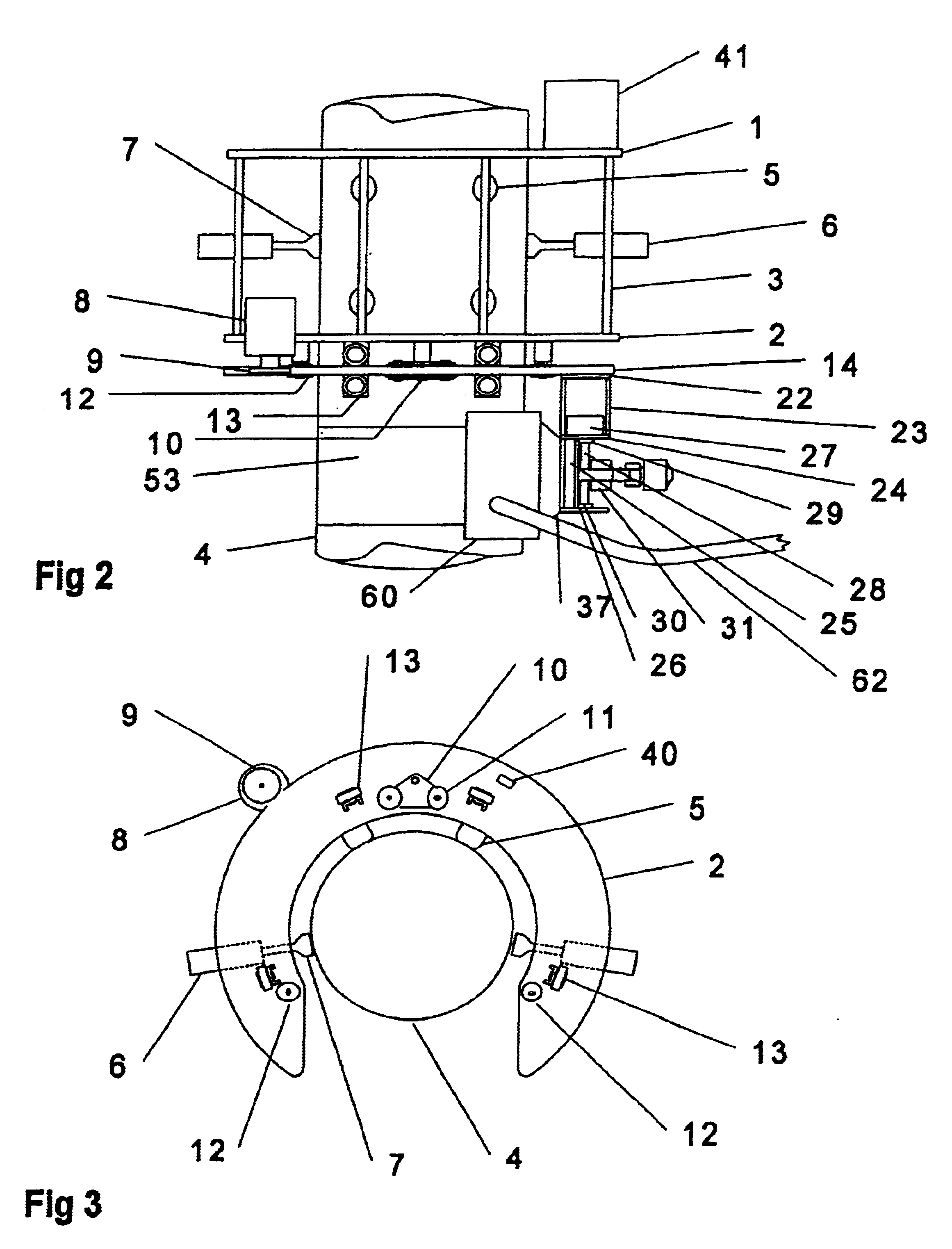
[0050]Referring to the drawings, the apparatus comprises two main parts, a stator shown separately in FIG. 3 and a rotor shown separately in FIG. 4. The stator comprises two horseshoe shaped plates 1 and 2 connected in a parallel, spaced apart manner by tie bars 3, so that the openings in each plate coincide. The shape of plates 1 and 2 enables the apparatus to be quickly lowered onto a pipe 4. Mounted on and fixed relative to each of the two uppermost (as illustrated, which is the normal orientation in which the apparatus would be used) tie bars 3 are two rubber faced feet 5 which support the stator when placed onto a pipe 4. Mounted on each of the two lower tie bars 3 is a pneumatic cylinder 6 which houses a piston connected to a rubber faced foot 7. The cylinders 6 are operative to move the feet radially inwards to clamp the stator onto a pipe 4, so that it is fixed relative to the pipe.

[0051]Also mounted on the stator is a pneumatic motor 8 arranged to drive a sprocket 9 the axi...


PUM

PropertyMeasurementUnit
lengthaaaaaaaaaa
thicknessaaaaaaaaaa
thicknessaaaaaaaaaa

Abstract

Apparatus for spraying a coating onto the outside of a pipe includes a body for mounting on a pipe to be coated. A spray gun is mounted on the body such that it can move relative to the body to spray coating completely around the periphery of the pipe. The apparatus may include only a single spray gun which is able to travel in a 360 degree range of motion around the periphery of the pipe. The apparatus is particularty suited to coating girth welds of a pipeline.

Description

APPARATUS AND METHOD FOR COATING PIPES[0001]This is a national stage application of PCT / GB00 / 04173, filed Oct. 30, 2000.[0002]The present invention relates to an apparatus and method for coating pipes and particularly, but not exclusively, to apparatus and methods for coating girth welds on oil and gas pipelines on site where the pipeline is being laid.BACKGROUND OF THE INVENTION[0003]Oil and gas pipelines are usually formed from many lengths of externally coated steel pipe which are welded together before they are laid. The pipes are coated to prevent corrosion and are usually coated at a factory remote from the site where they are to be laid. This is generally more cost effective than coating them at the site. At the factory coating is applied to the outside of the pipes leaving a short length, about 15 cm, uncoated at each end. This is necessary to enable the pipes to be welded together and to end on site to form a pipeline. Each resulting girth weld and adjacent uncoated region ...

Claims


Application Information

Patent Timeline
Patent Type & Authority Patents(United States)
IPC IPC(8): B05B15/02B05B13/02B05B13/04B05B15/55
CPCB05B13/0436B05B15/025Y10S118/11B05B15/55
Inventor DAYKIN, DAMIANHAM, DAVIDKELLY, ADRIANPEEL, DEREK JOHN
Owner PIPELINE INDUCTION HEAT
Why Eureka
Try Eureka