[0016]An
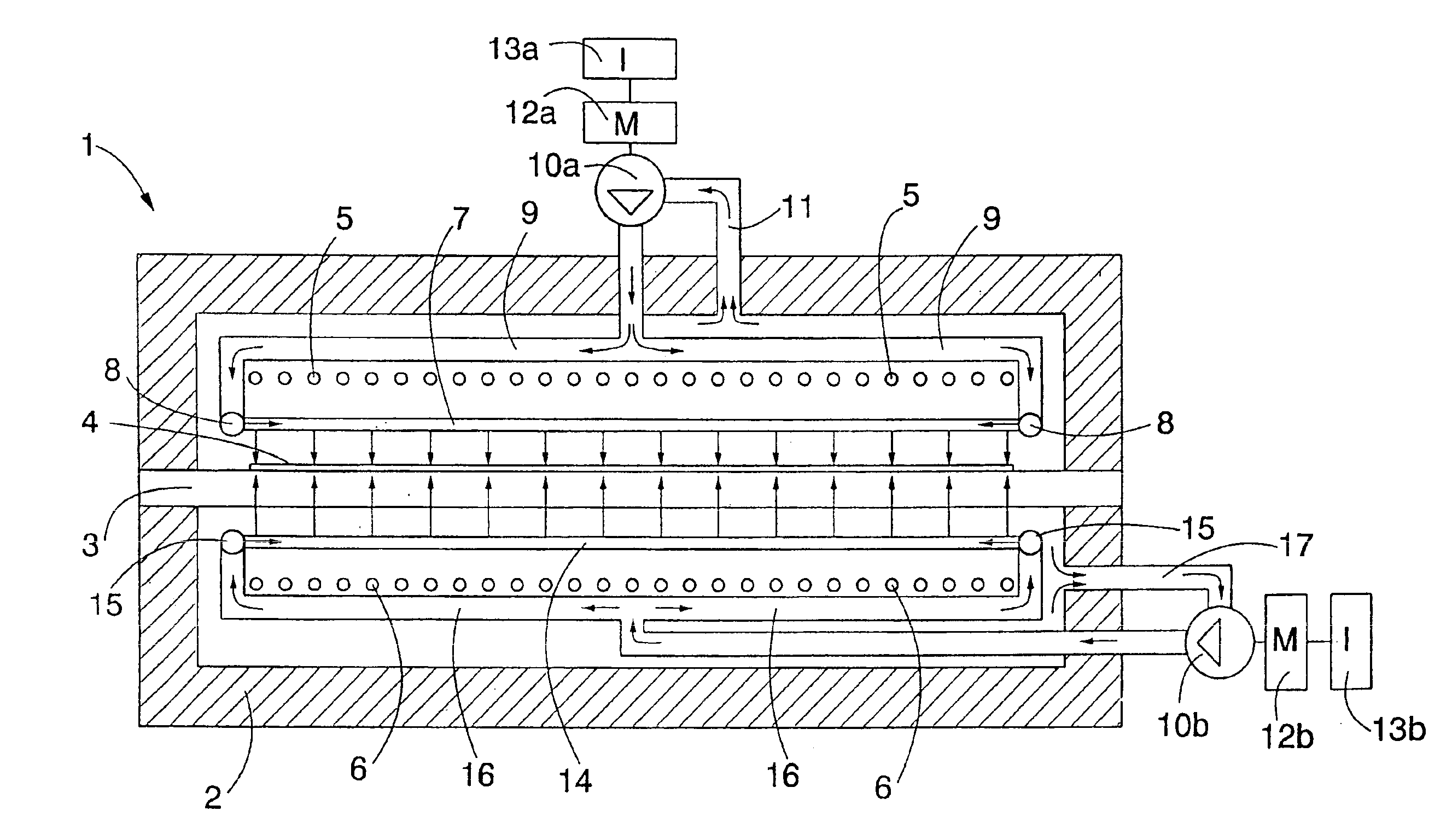
advantage of the invention is that since the
pressure level of the air is fairly high, a high
discharge velocity is achieved for the air, and at the same time, a very
high heat-transfer coefficient on the surface of the glass is achieved. Since the air blown is hot, air can be blown directly as far as onto the glass surface and air can also be blown until the end of the
heating cycle of the glass. Further, owing to the
high pressure level and the hot air,
high heat-transfer coefficients can be achieved with a small amount of air, whereby the
pipe system of the apparatus is small and simple and thus there are no risks what it comes to thermal movements. Since in the solution the air to be blown is taken from the inside of the furnace, the furnace has no problems that would be caused by the
discharge of excessive air. Further, the amount of air and at the same time the heat-transfer coefficient can be increased basically without limits. Increasing the amount of air and the heat-transfer coefficient can be performed simply by increasing the size of the pressurization unit, whereby the
heat losses of the furnace do not increase significantly. A significantly shorter
heating time is achieved for the glass by means of the method according to the invention. Particularly when selective glasses are heated, the
heating time can be made considerably shorter, because the solution according to the invention utilizes
convection heating in a very efficient manner, and the
radiation properties of the glass surface do not substantially weaken the effect of the
convection heating. What is known as a heating profile can be created for the furnace by means of electric resistors,
convection blowing having at the same time enabled the raising of the furnace capacity. Further, a furnace provided with a heating
resistor is very easy to keep in balance compared with for example convection furnaces where the intention is to implement the heating with mere air jets. In such solutions, the channel
system surfaces in the vicinity of the glass get cool compared with the rest of the area and may cause imbalance in the furnace. The solution is very easy to
mount afterwards, because the apparatus and its
pipe system are small in size and simple.
is that since the
pressure level of the air is fairly high, a high
discharge velocity is achieved for the air, and at the same time, a very
high heat-transfer coefficient on the surface of the glass is achieved. Since the air blown is hot, air can be blown directly as far as onto the glass surface and air can also be blown until the end of the
heating cycle of the glass. Further, owing to the
high pressure level and the hot air, high heat-transfer coefficients can be achieved with a small amount of air, whereby the
pipe system of the apparatus is small and simple and thus there are no risks what it comes to thermal movements. Since in the solution the air to be blown is taken from the inside of the furnace, the furnace has no problems that would be caused by the discharge of excessive air. Further, the amount of air and at the same time the heat-transfer coefficient can be increased basically without limits. Increasing the amount of air and the heat-transfer coefficient can be performed simply by increasing the size of the pressurization unit, whereby the
heat losses of the furnace do not increase significantly. A significantly shorter
heating time is achieved for the glass by means of the method according to the invention. Particularly when selective glasses are heated, the heating time can be made considerably shorter, because the solution according to the invention utilizes convection heating in a very efficient manner, and the
radiation properties of the glass surface do not substantially weaken the effect of the convection heating. What is known as a heating profile can be created for the furnace by means of electric resistors, convection blowing having at the same time enabled the raising of the furnace capacity. Further, a furnace provided with a heating
resistor is very easy to keep in balance compared with for example convection furnaces where the intention is to implement the heating with mere air jets. In such solutions, the channel system surfaces in the vicinity of the glass get cool compared with the rest of the area and may cause imbalance in the furnace. The solution is very easy to
mount afterwards, because the apparatus and its pipe system are small in size and simple.

