Supercharge Your Innovation With Domain-Expert AI Agents!

Production of a cylindrical housing for a double screw extruder

a technology of extruder and cylindrical housing, which is applied in the direction of electric/magnetic/electromagnetic heating, heat treatment apparatus, furnaces, etc., can solve the problems of inability to produce cylindrical housings. to achieve the effect of reducing heat loss, avoiding undesired through hardening of large parts of the narrowed region, and less thermal energy

Inactive Publication Date: 2005-04-19
KRAUSSMAFFEI BERSTORFF GMBH
View PDF4 Cites 2 Cited by
  • Summary
  • Abstract
  • Description
  • Claims
  • Application Information

AI Technical Summary

Benefits of technology

[0010]In accordance with the invention, after the spectacle-shaped bore has been produced in the steel block used for the production of the barrel or barrel segment, the inner surface of the spectacle-shaped bore is hardened by inductive hardening. The depth of penetration is essentially maintained at a constant value by using an electrical inductor that is smaller than, but has approximately the same shape as, the inner contour of the spectacle-shaped bore and is passed through the spectacle-shaped bore from one end of the bore to the other. In accordance with the invention, this inductor is configured in such a way that significantly less energy for heating the inner surface of the spectacle-shaped bore is delivered in the vicinity of the two narrowed regions of the spectacle-shaped bore with respect to the associated longitudinal section on the periphery of the inductor than in the regions of the inner contour more remote from the narrowed regions. Consequently, the individual volume elements near the narrowed regions, which are close to both of the barrel bores and therefore receive heat input via the inner surface of both bores, are heated less intensely than if there were equal thermal energy input (specific thermal energy input) everywhere with respect to the inner surface of the barrel bores. The specific thermal energy input can be metered in such a way that the heating that occurs in each narrowed region, at least approximately in the material zone that is close to the inner surface and that is intended for hardening, is approximately equally intense as the heating that occurs in the surface regions more distant from the two narrowed regions. In this way, the undesired through-hardening of large parts of the narrowed region can be avoided. Thus, the desired ductility in the volume parts of the barrel wall farther from the bore surfaces is also maintained to the specific extent required in the narrowed region.
[0012]The specific thermal energy input in the vicinity of the two narrowed regions of the spectacle-shaped bore can be reduced in a variety of ways. In one embodiment, the invention provides that the inductor be guided through the barrel bores at a significantly greater distance from the inner surface in the vicinity of the two narrowed regions, compared to the remaining region of the inner contour of the spectacle-shaped bore. The greater the distance of the inductor from the inside surface of the barrel, the less thermal energy can be produced by the inductor in the given surface region.
[0017]Preferably, an inductor is formed as a continuous electrical conductor, which has the approximate outer shape of a “figure 8,” by bending an electrically conductive tube, preferably a copper tube. A coolant can be passed through this tube to cool the inductor. The inductor is shaped in such a way that the upper and lower regions of the “figure 8” are each bent into a circular shape, while a region with a decreasing radius of curvature follows these upper and lower circular regions as the curve approaches closer and closer to the middle region of the “figure 8”, which corresponds to the narrowed region of the spectacle-shaped bore. In the actual middle region of the “figure 8”, an oppositely curved section is provided on each side to join the regions with the smaller radius of curvature with each other in pairs. The variation of the radius of curvature has the effect that the given subregions on the periphery of the inductor have different distances from the inner surface as the inductor passes through the spectacle-shaped bore of the barrel.

Problems solved by technology

The inner surface of the barrel bore is subject to abrasive wear, which has basically two causes.
The first cause is the processing of feedstocks with aggressive properties, e.g., plastics that contain abrasive fillers.
The second cause is related to the pressure conditions that arise inside the barrel during processing, which can lead to radial deflections of the screw shaft and thus to sliding contact between the outer surface of the screw and the inner surface of the barrel.
This produces through-hardening of the workpiece, which is usually undesirable.
Specifically, at these points it is desirable for the barrel to have the best possible toughness properties to avoid fractures, but toughness properties are generally lost as a result of through-hardening.
In addition, the costs of this type of hardening treatment are relatively high, because the hardening treatment depends primarily on the weight of the workpieces, and a barrel segment for a twin-screw extruder is very heavy due to the thick walls that are required.
However, these types of processes are especially expensive due to the long annealing times that are required.
In the latter case, electric eddy currents are induced by an inductor in the workpiece to be treated, which cause heating, especially due to the magnetic reversal of the workpiece.
Of course, in the case of barrels for twin-screw extruders, inductive heating by means of an inductor with a shape corresponding to the shape of the barrel cross section would lead to extremely nonuniform heating and depths of penetration.
The result of this would be that these regions would become especially susceptible to fracture.

Method used


Image

  • Production of a cylindrical housing for a double screw extruder
  • Production of a cylindrical housing for a double screw extruder
  • Production of a cylindrical housing for a double screw extruder

Examples


Embodiment Construction

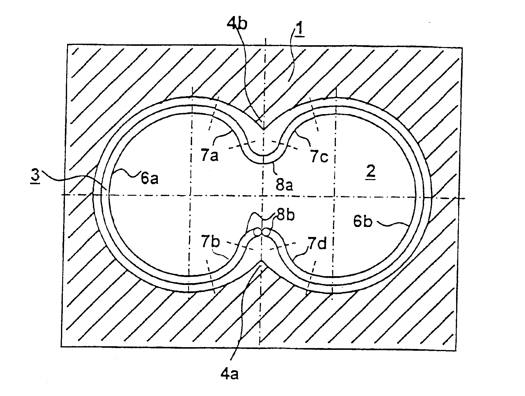
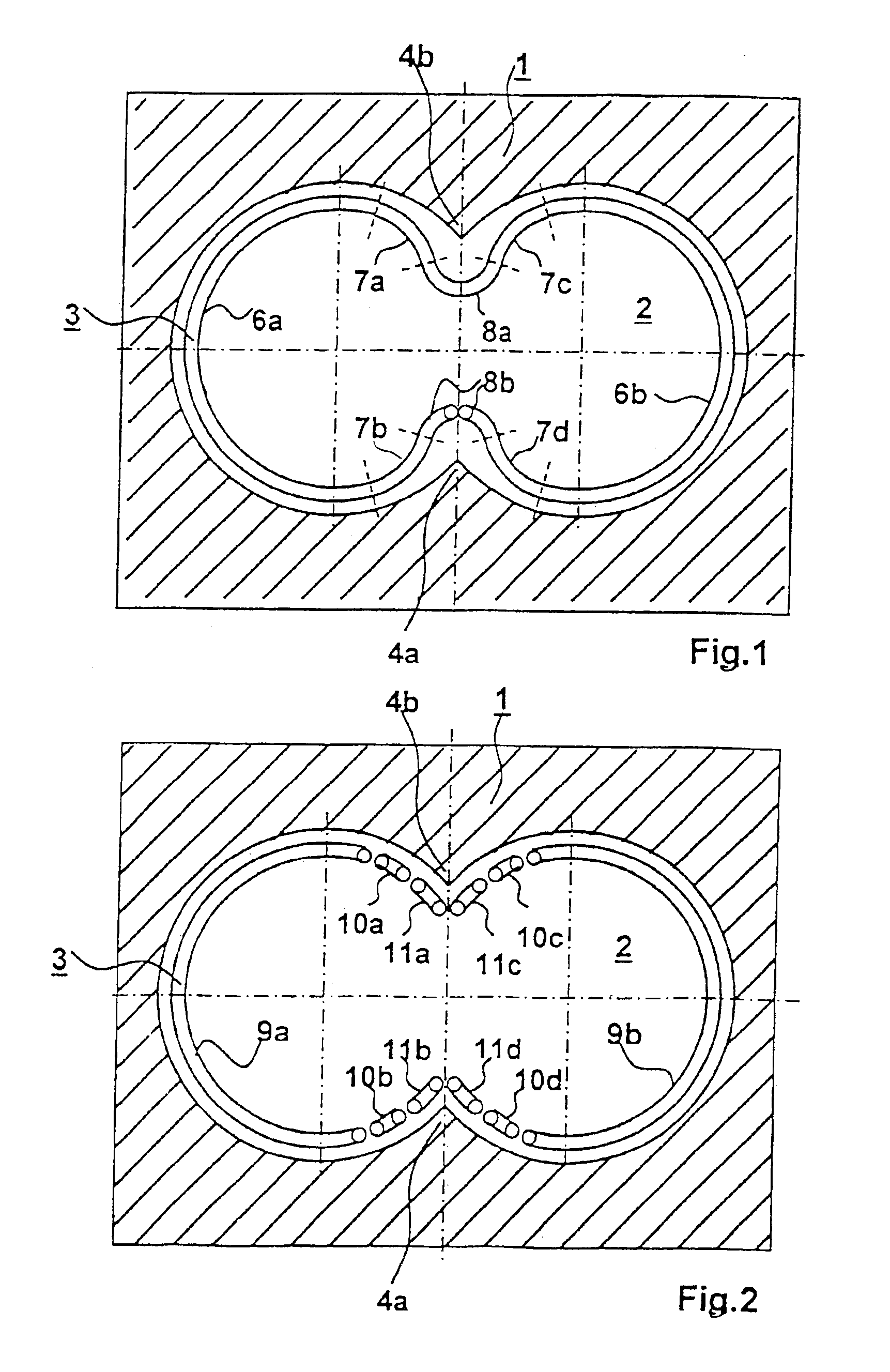
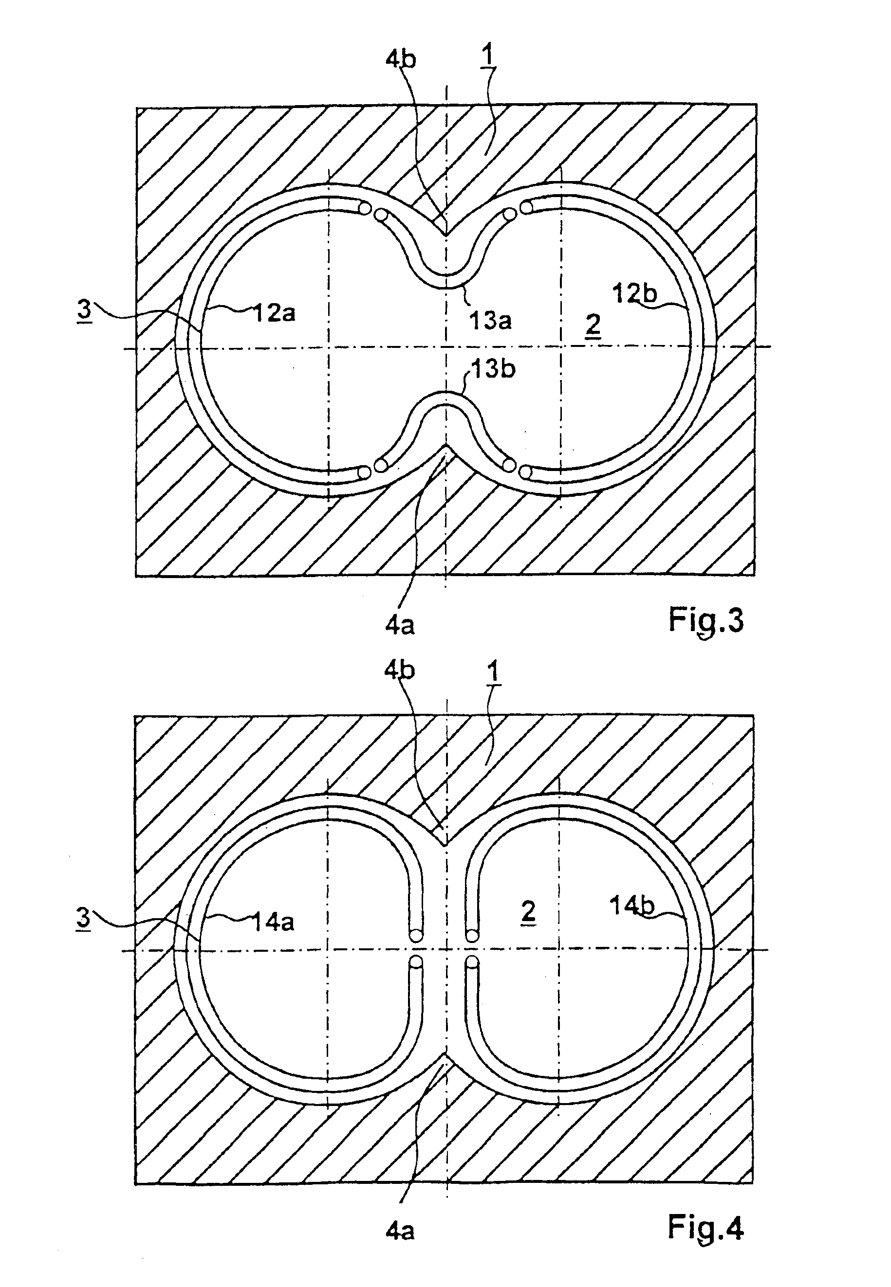
[0024]Each of FIGS. 1 to 4 shows a cross section of a barrel 1 with a spectacle-shaped bore 2 formed from two intersecting barrel bores. The barrel 1 was produced from a block of hardenable steel by machining production methods. In the intersecting region of the two barrel bores, the barrel wall is shaped in the form of the two narrowed regions 4a, 4b. A narrowing of this type is shown as an enlarged section in FIG. 6. The inner surface of the barrel 1 is to be hardened in such a way that the hardened layer 17 has only a very limited depth of, for example, 0.5-2 mm. This is intended to prevent the narrowed regions 4a, 4b from becoming through-hardened and thus losing their ductility in their interiors. A plating 18 of high grade hardenable material may be applied to an inner surface of the barrel before machining of the spectacle-shaped bore is complete. When present, the plating comprises at least a part of the hardened layer 17.

[0025]The interior of the spectacle-shaped bore 2 in ...


PUM

PropertyMeasurementUnit
Wear resistanceaaaaaaaaaa
Radiusaaaaaaaaaa
Distanceaaaaaaaaaa

Abstract

A process for producing a barrel for a twin-screw extruder with intermeshing screws from a steel block, wherein the barrel has a wear resistant inner surface, includes producing two partially intersecting bores passing completely through the steel block, the two intersecting bores forming a spectacle-shaped bore having narrowed regions where the two intersecting bores intersect, and hardening an inner surface of the spectacle-shaped bore with essentially constant depth of penetration by passing an inductor through the spectacle-shaped bore from one end to the other, the inductor is smaller than but having approximately the same shape as the inner contour of the spectacle-shaped bore and is configured such that less energy for heating the inner surface of the spectacle-shaped bore is delivered in the vicinity of the two narrowed regions of the spectacle-shaped bore by the longitudinal sections on the periphery of the inductor than in regions on the inner contour remote from the narrowed regions.

Description

PRIORITY CLAIM[0001]This is a U.S. national stage of application No. PCT / DEO2 / 00876, filed on Mar. 07, 2002. Priority is claimed on that application and on the following application(s): Country: Germany, Application No.: 101 12 295.0, Filed: Mar. 08, 2001.BACKGROUND OF THE INVENTION[0002]1. Field of the Invention[0003]The invention relates to a process for producing a barrel with a wear-resistant inner surface from a steel block for a twin-screw extruder with intermeshing screws, the process including the steps of producing two partially intersecting bores (i.e., forming a bore with a spectacle-shaped cross section) that pass all the way through the steel block, followed by hardening of the inner surface of the spectacle-shaped bore. The invention also relates to equipment for hardening the inner surface of the spectacle-shaped bore.[0004]2. Description of the Prior Art[0005]Twin-screw extruders with tightly intermeshing screws have barrels made of partial axial segments with a spec...

Claims


Application Information

Patent Timeline
IPC IPC(8): C21D9/08C21D1/10C21D1/09B29C47/66C21D9/00
CPCC21D1/10C21D9/08Y10T29/4927Y02P10/25
Inventor BEHLING, MICHAELWESLING, VOLKERMOTZKAU, UWE
Owner KRAUSSMAFFEI BERSTORFF GMBH
Features
  • R&D
  • Intellectual Property
  • Life Sciences
  • Materials
  • Tech Scout
  • Unparalleled Data Quality
  • Higher Quality Content
  • 60% Fewer Hallucinations
Learn More