
Oil and gas recovery articles

a technology for oil and gas recovery and articles, applied in the direction of sealing/packing, drilling pipes, and well accessories, can solve the problems of affecting the the electrical performance of certain oil and gas article parts such as for example electrical connectors, switches, circuit breakers, etc., and the electrical performance of certain oil and gas article parts, etc., to achieve the effect of enhancing the mechanical performance of unfilled (paek) polymers, increasing the dielectric strength

Pending Publication Date: 2020-05-21
SOLVAY SPECIALTY POLYMERS USA LLC
View PDF7 Cites 0 Cited by
  • Summary
  • Abstract
  • Description
  • Claims
  • Application Information

AI Technical Summary

Benefits of technology

The patent describes the addition of nitride (NI) to (PAEK) polymers and the improvement in mechanical performance, especially the dielectric strength, when processed by injection molding. The addition of nitride also enhances the stiffness and maintains ductility of the polymer, making it useful in oil and gas recovery applications. Additionally, the reduced coefficient of linear thermal expansion (CLTE) ensures greater dimensional stability during thermal cycling and reduces thermally induced stresses under the expected temperature swings during operation.

Problems solved by technology

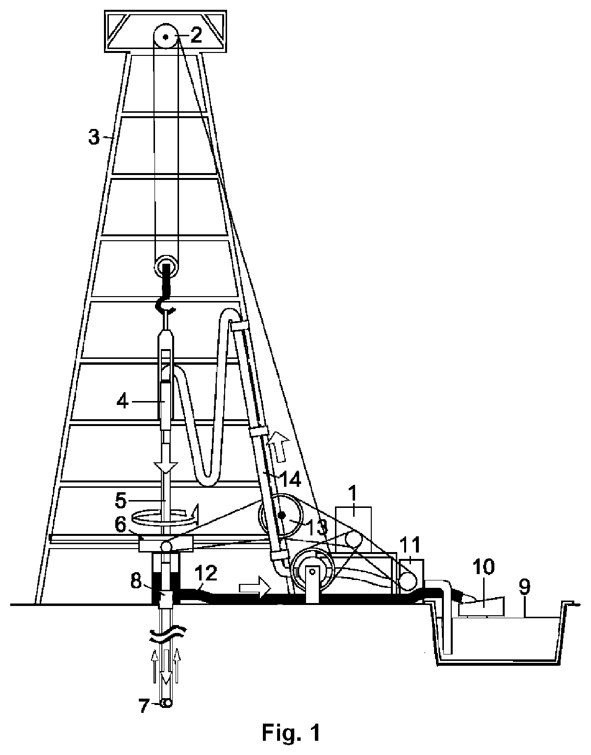
Said harder-to-reach oil fields are often associated with the most challenging operating environments, such as much of which is deep under the ocean and under high pressure.
It is a critical challenge for the oil and gas market that articles including high performance polymers suitable for use in oil and gas recovery application, for example as notably used in high pressure and high temperature [HP / HT, used herein after] deepwater oil and gas recovery applications, resist these extreme conditions of being exposed in a prolonged fashion to high pressure, e.g. pressures higher than 30,000 psi, high temperatures e.g. temperatures up to 260° C. to 300° C. and to harsh chemicals including acids, bases, superheated water / steam, and of course a wide variety of aliphatic and aromatic organics.
In particular, sCO2 having a solvating effect similar to n-heptane, can cause swelling of materials in for instance seals, which affect consequently their performance.
Additionally, the electrical performance of certain oil and gas article parts such as for example electrical connectors, switches, circuit breakers, housings, wire and cables and the like, also need to be challenged in these extreme conditions, as described above.
It is also generally known that the stiffness of (PAEK) polymers can be increased by adding stiff materials such as reinforcing fillers, in particular glass fibers or carbon fibers but it has some drawbacks such as notably that said reinforced compositions often turn brittle.
Another disadvantage of reinforcements like glass fibers and carbon fibers is the well known anisotropy effect of these materials.
The anisotropic nature of bulk fiber reinforced plastics like glass fiber and carbon fiber, for example is that the composition has non-uniform properties over the various locations of the part, depending on how the fibers are oriented.
The strong anisotropy just mentioned also leads to warpage issues in injection molded parts as different portions or dimensions of the part may shrink differently depending on the state of fiber alignment in that particular direction.
In these cases, the use of a glass fiber reinforced resin with a relatively high loading of glass reinforcement (i.e. 20% or more) can become disadvantageous from a unit weight and mobility standpoint as these reinforcements significantly increase the density of the composition relative to the corresponding unfilled polymer.
Carbon fiber can mitigate this effect due to its lower density relative to glass fiber, but on the other hand carbon fiber-reinforced plastics have some level of electrical conductivity which can be a problem in end uses where good electrical insulation is desired.

Method used


Image

  • Oil and gas recovery articles
  • Oil and gas recovery articles
  • Oil and gas recovery articles

Examples


Embodiment Construction

(C1)Example 7DirectionCLTE at Temperature RangeFlowTransverseFlowTransverse−50-0° C. (ppm / ° C.)35.145.424.435.70-50° C. (ppm / ° C.)40.449.026.240.450-100° C. (ppm / ° C.)43.654.028.346.1100-150° C. (ppm / ° C.)45.957.729.350.6Average −50 to +150° C.41.251.627.143.2(ppm / ° C.)% Reduction Relative——3316to comparative example (C1)Overall % Reduction Relative—25to comparative example (C1)**Average of reductions in flow and transverse directions

ADDITIONAL EXAMPLES

[0166]Test specimens for performing ASTM mechanical properties were prepared by two different methods: 1) direct injection molding into 0.125 in (3.2 mm) thick ASTM tensile and flexural specimens and 2) extrusion into 1 inch diameter rod stock of the formulation followed by machining 0.125 in (3.2 mm) thick tensile and flexural specimens from the center of the extruded rods. Extruded and machined specimens were tested alongside the injection molded ones. The parts tested for comparative examples 1-3 and example 7 have thus the exact s...


PUM

PropertyMeasurementUnit
wt. %aaaaaaaaaa
wt. %aaaaaaaaaa
particle sizeaaaaaaaaaa

Abstract

An oil and gas recovery article comprising at least one part made from injection molding a composition [composition (C)] consisting essentially of, from 50 to 99.5% by weight (wt. %) of at least one polyaryletherketone polymer [(PAEK) polymer, herein after]; from 0.5 to 15.0% by weight (wt. %) of at least one nitride (NI) of an element having an electronegativity (c) of from 1.3 to 2.5, as listed in «Handbook of Chemistry and Physics», CRC Press, 64th edition, pages B-65 to B-158; and from 0 to 35.0% by weight (wt. %) of at least one optional ingredient selected from the group consisting of selected from the group consisting of colorants, pigments, light stabilizers, heat stabilizers, antioxidants, acid scavengers, processing aids, nucleating agents, internal lubricants and / or external lubricants, flame retardants, smoke-suppressing agents, anti-static agents, anti-blocking agents, conductivity additives and reinforcing additives, all wt. % are relative to the total weight of the composition (C).

Description

CROSS-REFERENCE TO RELATED APPLICATION[0001]This application is a divisional application claiming priority benefit from U.S. non-provisional application Ser. No. 15 / 103,129, which a 371 national phase application of International application No. PCT / EP2014 / 078113, which claims priority to U.S. provisional application No. 61 / 917,614 filed Dec. 18, 2013, and to European application No. 14165228.9 filed Apr. 17, 2014, the whole content of these applications being incorporated herein by reference for all purposes.FIELD OF INVENTION[0002]The present invention is related to an article suitable for use in oil / gas recovery industries comprising at least one structural part made by injection molding a poly(aryletherketone) polymer composition wherein said injection molded structural part of said poly(aryletherketone) polymer composition is characterized by having improved mechanical properties, in particular high stiffness and high toughness, increased dielectric strength, dimensional stabil...

Claims


Application Information

Patent Timeline
Patent Type & Authority Applications(United States)
IPC IPC(8): C08K3/38E21B43/12E21B34/00E21B33/12E21B17/00E21B4/00B29C45/00C08K3/013C08K3/28
CPCE21B34/00C08K3/28C08K3/013E21B4/00C08K2003/385E21B33/12B29C45/0001E21B17/00B29K2105/0005E21B43/121C08K3/38B29K2071/00C08L71/12
Inventor EL-HIBRI, MOHAMMAD JAMAL
Owner SOLVAY SPECIALTY POLYMERS USA LLC
Learn More