
Method of correction for wafer crystal cut error in semiconductor processing

Inactive Publication Date: 2005-04-19
AXCELIS TECHNOLOGIES
View PDF3 Cites 15 Cited by
  • Summary
  • Abstract
  • Description
  • Claims
  • Application Information

AI Technical Summary

Benefits of technology

[0008]The present invention is directed to accounting for crystal cut error data in ion implantation systems, thereby facilitating more accurate ion implantation. One or more aspects of the invention also consider possible shadowing effects that can result from features formed on the surface of a wafer being doped. According to one or more aspects of the invention, crystal cut error data and optionally feature data also are periodically fed forward in one or more ion implantation stages or systems to ascertain how to re-orient the ion beam with respect to the workpiece to achieve desired implantation results.
[0012]To the accomplishment of the foregoing and related ends, the following description and annexed drawings set forth in detail certain illustrative aspects and implementations of the invention. These are indicative of but a few of the various ways in which one or more aspects of the present invention may be employed. Other aspects, advantages and novel features of the invention will become apparent from the following detailed description of the invention when considered in conjunction with the annexed drawings.

Problems solved by technology

However, while much thought and consideration is usually given to the orientation (e.g., tilt and / or twist, etc.) of the ion beam relative to the wafer, ion implantation systems generally orient the ion beam relative to the mechanical surface of a wafer, with little to no consideration given to variations between the wafer's internal lattice structure and its mechanical surface.
In either instance, improper alignment can lead to undesired degrees of channeling (e.g., too little or too much).
Additionally, the deviations from the nominal lattice orientation and the dimensions of features formed upon the wafer can affect shadowing, and adversely impact the implantation process and resulting devices.

Method used


Image

  • Method of correction for wafer crystal cut error in semiconductor processing
  • Method of correction for wafer crystal cut error in semiconductor processing
  • Method of correction for wafer crystal cut error in semiconductor processing

Examples


Embodiment Construction

[0022]One or more aspects of the present invention are described with reference to the drawings, wherein like reference numerals are generally utilized to refer to like elements throughout, and wherein the various structures are not necessarily drawn to scale. In the following description, for purposes of explanation, numerous specific details are set forth in order to provide a thorough understanding of one or more aspects of the present invention. It may be evident, however, to one skilled in the art that one or more aspects of the present invention may be practiced with a lesser degree of these specific details. In other instances, well-known structures and devices are shown in block diagram form in order to facilitate describing one or more aspects of the present invention.

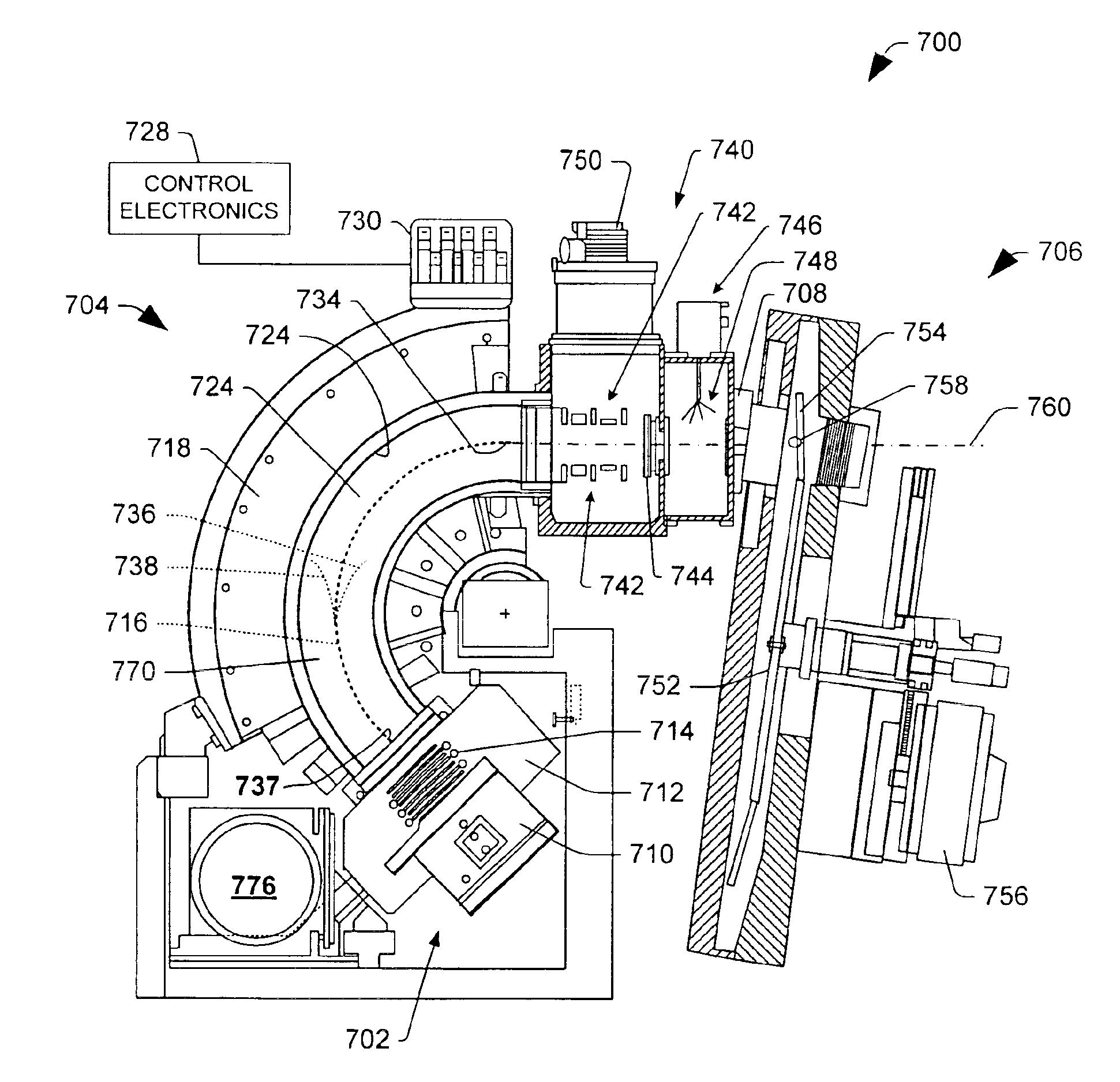
[0023]The present invention is directed to accounting for crystal cut error data in ion implantation systems, thereby facilitating more accurate ion implantation. One or more aspects of the invention also cons...


PUM


Abstract

The present invention is directed to accounting for crystal cut error data in ion implantation systems, thereby facilitating more accurate ion implantation. One or more aspects of the invention also consider possible shadowing effects that can result from features formed on the surface of a wafer being doped. According to one or more aspects of the invention, crystal cut error data and optionally feature data also are periodically fed forward in one or more ion implantation stages or systems to ascertain how to re-orient the ion beam with respect to the workpiece to achieve desired implantation results.

Description

FIELD OF THE INVENTION[0001]The present invention relates generally to ion implantation systems, and more particularly to accounting for wafer cut error as may affect ion implantation in semiconductor fabrication.BACKGROUND OF THE INVENTION[0002]Ion implantation systems are the mechanisms utilized to dope semiconductor substrates with dopants or impurities in integrated circuit manufacturing. In such systems, a dopant material is ionized and an ion beam is generated there-from. The ion beam is directed at the surface of a semiconductor wafer in order to implant the wafer with the dopant element. The ions of the beam penetrate the surface of the wafer to form a region of desired conductivity, such as in the fabrication of transistor devices in the wafer. A typical ion implanter includes an ion source for generating the ion beam, a beamline assembly including a mass analysis apparatus for directing and / or filtering (e.g., mass resolving) the ions within the beam using magnetic fields,...

Claims


Application Information

Patent Timeline
IPC IPC(8): H01L21/265H01J37/147H01J37/317H01L21/02
CPCB32B3/02H01J2237/1501Y10T428/21Y10S414/135H01J2237/31701H01L21/00
Inventor RAY, ANDREW M.
Owner AXCELIS TECHNOLOGIES
Learn More