Apparatus, system and method for enabling eye-to-eye contact in video conferences

a technology of eye-to-eye contact and video conference, which is applied in the field of video conference, can solve the problems of exacerbated problems, no longer able to easily view the video display, and inability to achieve eye-to-eye conta

Inactive Publication Date: 2005-04-19
GOOGLE LLC
View PDF17 Cites 137 Cited by
  • Summary
  • Abstract
  • Description
  • Claims
  • Application Information

AI Technical Summary

Benefits of technology

[0006]In accordance with a first aspect of the invention, the apparatus employs a partially-reflective plate disposed in front of a video display to produce a reflected image of a target object or objects, typically comprising one or more video conference participants. The reflected image is formed from a portion of light reflected off of the target object(s) received by the partially-reflective plate and reflected toward a vide...

Problems solved by technology

As a result, the conference participants rarely look directly at the video camera in their respective video conference rooms, and when they do so, they are no longer able to easily view their video display.
Thus, although the participants may see each other at times, they cannot achieve eye-to-eye contact.
This problem is exacerbated by today's larger video monitors and projection screens, since this forces the angle between the camera direction and the conference participants' focal direction ...

Method used


Image

  • Apparatus, system and method for enabling eye-to-eye contact in video conferences
  • Apparatus, system and method for enabling eye-to-eye contact in video conferences
  • Apparatus, system and method for enabling eye-to-eye contact in video conferences

Examples


first embodiment

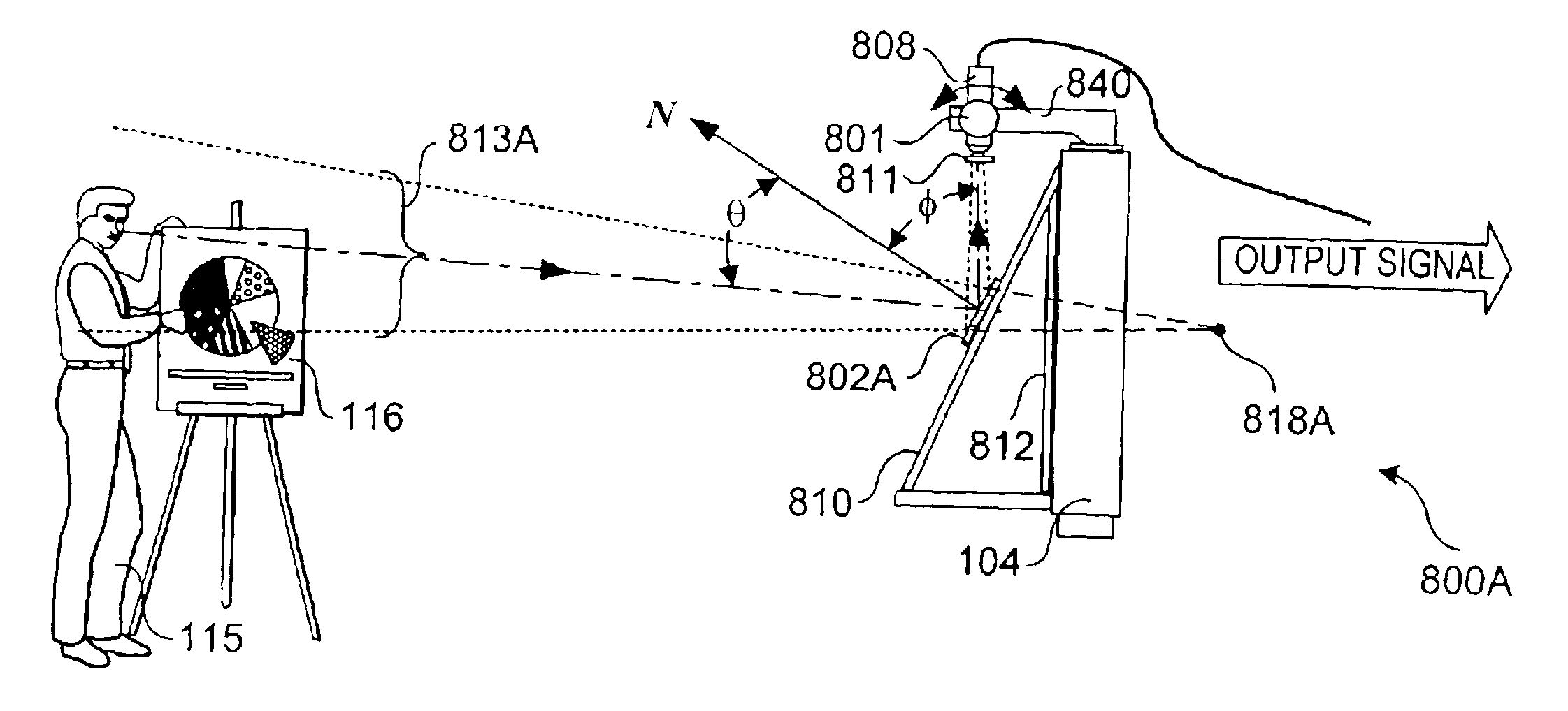
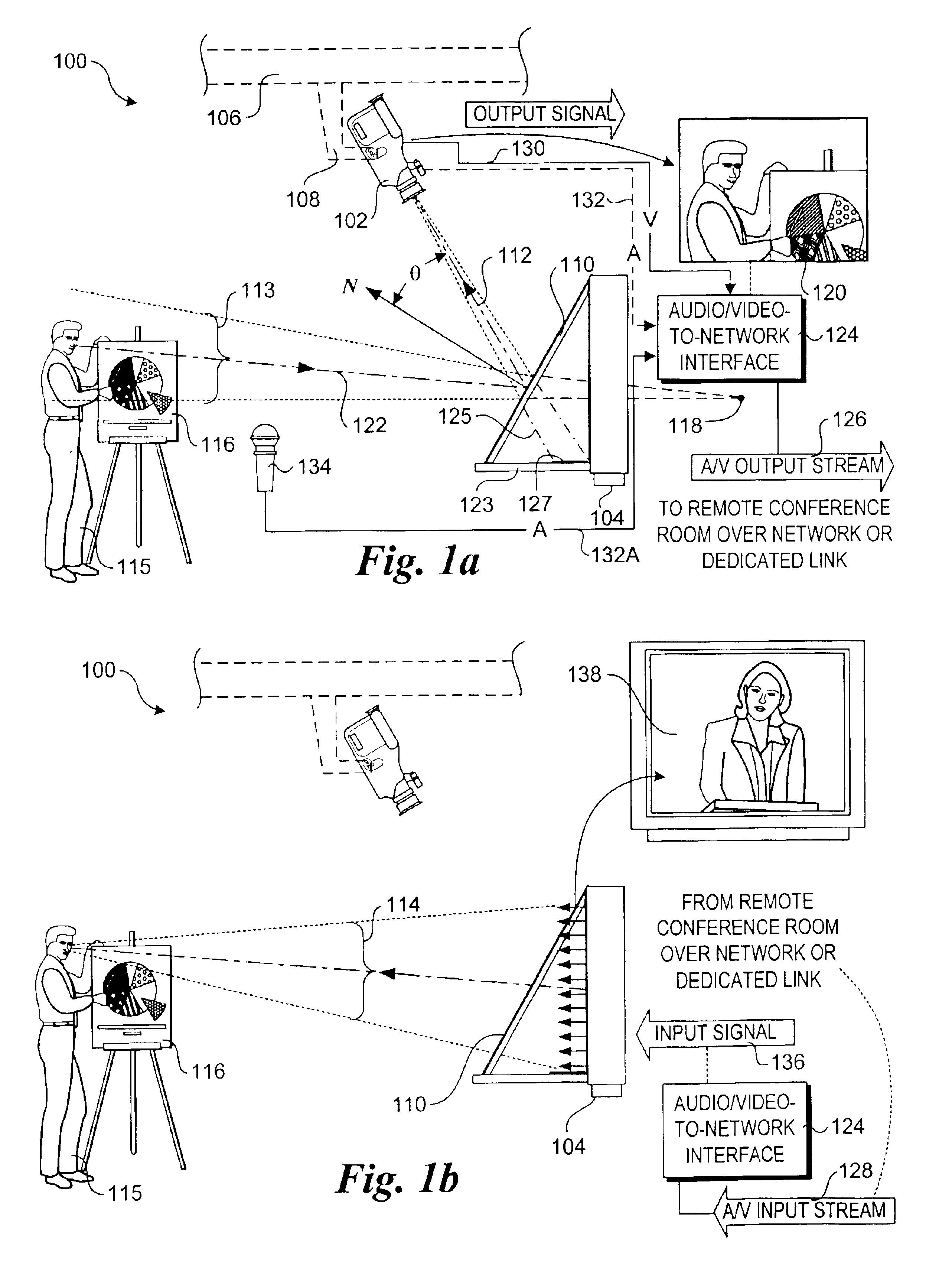
[0029]A video conference system 100 in accordance with the invention employing a reflective imaging scheme is shown in FIGS. 1a and 1b. The system includes a video camera 102 and a video display 104. Although depicted as a camcorder for convenience, video camera 102 may comprise any type of video unit capable of producing a video output signal in response to received light, such as conventional video cameras, optical fiber cameras, pinhole video cameras, remote video cameras, surveillance video cameras, etc. Similarly, video display 104 may comprise any display device capable of displaying a video image, including but not limited to a television, computer or television monitor, flat panel display, plasma display, and projection screen monitor.

[0030]Generally, video camera 102 will be mounted to a fixed surface or structure; in the illustrated embodiment it is mounted to the ceiling 106 of a conference room via a camera mount 108. The video camera mount may be a fixed mount, or a may...

embodiment 300

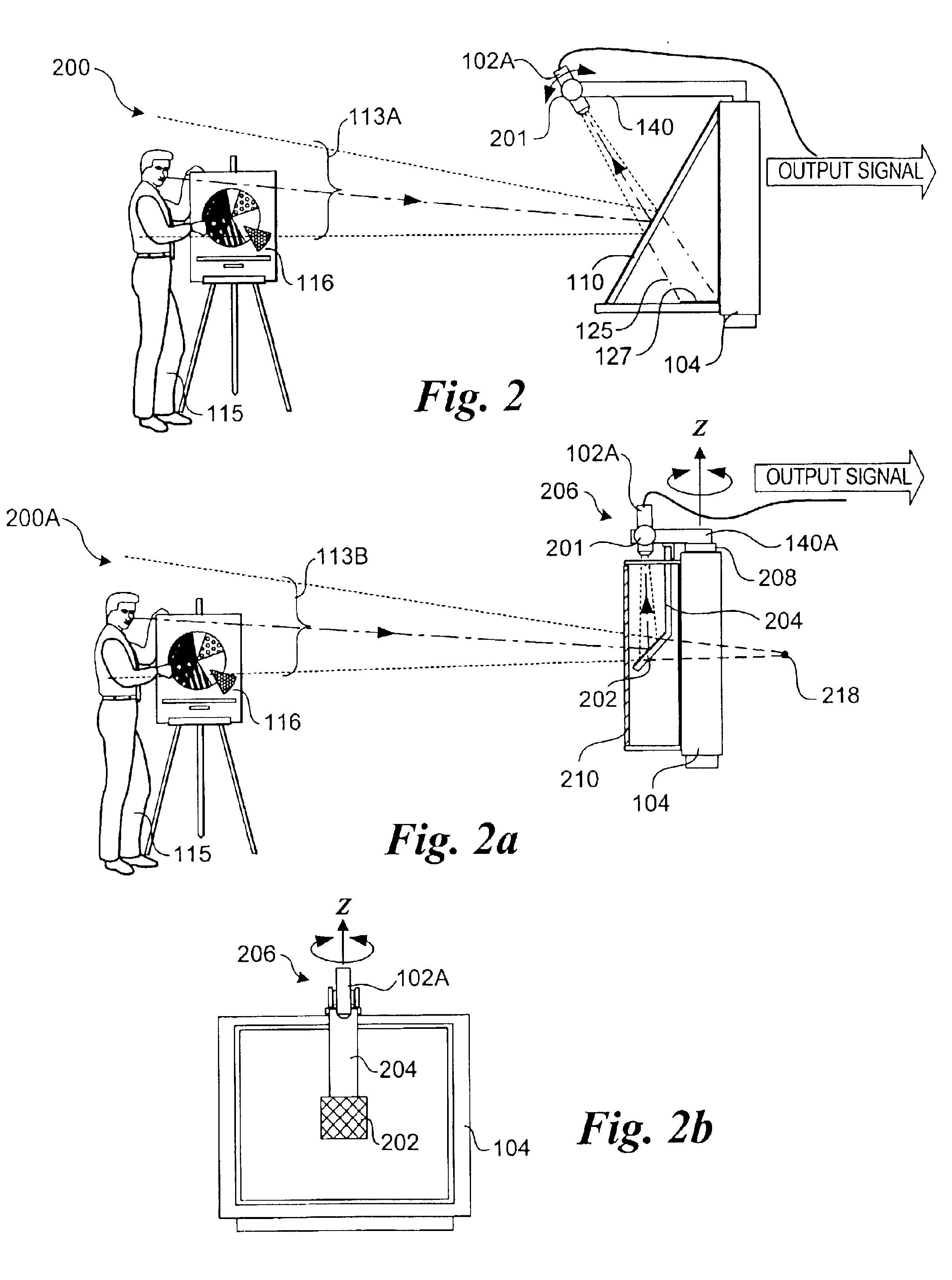
[0044]Another video teleconference system embodiment 300 is shown in FIG. 3. As with systems 200 and 200A, this embodiment preferably employs a small footprint video camera 102B. However, in this instance the system employs a secondary reflector 302 that enables the video camera to be deployed proximate to the video display. As depicted by light ray envelope 113C, light reflected off of the target objects in the video conference room, such as a participant 115 and visual aid 116 is received by partially-reflective plate 110, whereupon the light is first reflected toward secondary reflector 302, and then in turn reflected toward video camera 102B. If desired, the entire assembly may be disposed within a housing 304 which may include a window 306.

[0045]In a manner similar to that employed in systems 100 and 100A, video camera 102B, mirror 302, and partially-reflective plate 110 are configured such that a virtual extended FOV 127A of the video camera is directed such that is doesn't in...


PUM


Abstract

Apparatus, system, and method for enabling eye-to-eye contact in video conferences. In general, the system and apparatus employ means for generating video images corresponding to real images that would be produced if a video camera were disposed at or behind a video display having a field of view directed toward a target object such as a participant. An image (either real, reflected, or holographic) is formed based on light reflected off of the target object, and object light corresponding to the image is received by the video camera, which produces a video signal containing the image. Typically, the means for generating the video images employs direct imaging, reflective imaging, or holographic imaging. The means for generating the video images are also configured in such a manner as to be substantially transparent to video conference participants viewing the display images on the video display. A similar configuration is deployed at two or more conference rooms, thereby enabling participants to communicate with one another using eye-to-eye contact.

Description

FIELD OF THE INVENTION[0001]The field of invention relates generally to video conferencing and, more specifically but not exclusively relates to apparatus, systems and methods for performing video conferencing whereby participants are provided with eye-to-eye contact.BACKGROUND INFORMATION[0002]Recent gains in broadband access has fueled the increasing use of video (tele)conferencing. Video conferencing enables participants at various geographical locations to “meet” at a “virtual” conference that is facilitated via high-speed communication networks and corresponding video conferencing equipment at each conference location. For instance, basic video conferencing equipment typically includes an audio and video subsystem at each location, wherein the video subsystem generally comprises a video camera and a video display (e.g., monitor or video projector and projection screen. The video camera is used to transmit video images of local participants and visual aids to a remote location (...

Claims


Application Information

Patent Timeline
IPC IPC(8): H04N7/14
CPCH04N7/144
Inventor SCHUSTER, JOHNPIERCE, ROBERTBAJORINS, DAVID
Owner GOOGLE LLC
Why Eureka
Try Eureka