
Fiber Optic Interrogated Microslide, Microslide Kits and Uses Thereof

a fiber optic interrogation and microslide technology, applied in the field of fiber optic interrogation microslide, can solve the problems of difficult poor image quality, and difficulty in focusing through the thickness of the glass microscope slid

Inactive Publication Date: 2009-06-25
INCOM INC
View PDF4 Cites 25 Cited by
  • Summary
  • Abstract
  • Description
  • Claims
  • Application Information

AI Technical Summary

Benefits of technology

[0009]An embodiment of the present invention provides a substrate material that eliminates the problems (e.g., substrate thicknesses) associated with viewing a conventional plain microscope slide or microarray, or microtiter plate.
[0010]Another embodiment of the present invention provides a substrate material that eliminates the adverse optical effects of substrate thickness, allowing the substrate to be fabricated without regard to thickness (1,000 microns—0.039″ or thicker for example), which can eliminate the distortion effects that are typical of thin (150 micron—0.006″) conventional substrates.
[0011]Another embodiment provides a microscope slide, microarray or microtiter plate substrate material of the invention that allows direct imaging onto a CCD reader, minimizing the need for costly optics.

Problems solved by technology

Because of the finite thickness of a microscope slide, glass bottomed microtiter plate, or the bottom of the container, a standard higher power objective may not be able to get close enough to the subject to focus.
Even with all these corrections, the quality of the image may not be as good as looking through a conventional (top down) microscope with comparable objectives.
Furthermore, focusing through the thickness of the glass microscope slide, or glass bottomed microtiter plate becomes challenging.
While minimizing thickness issues, these bottoms lack rigidity creating issues associated with flatness.
Other distortions arise as a result of the fact that the glass and plastic are not expansion matched which cause the glass to warp from one area to another.
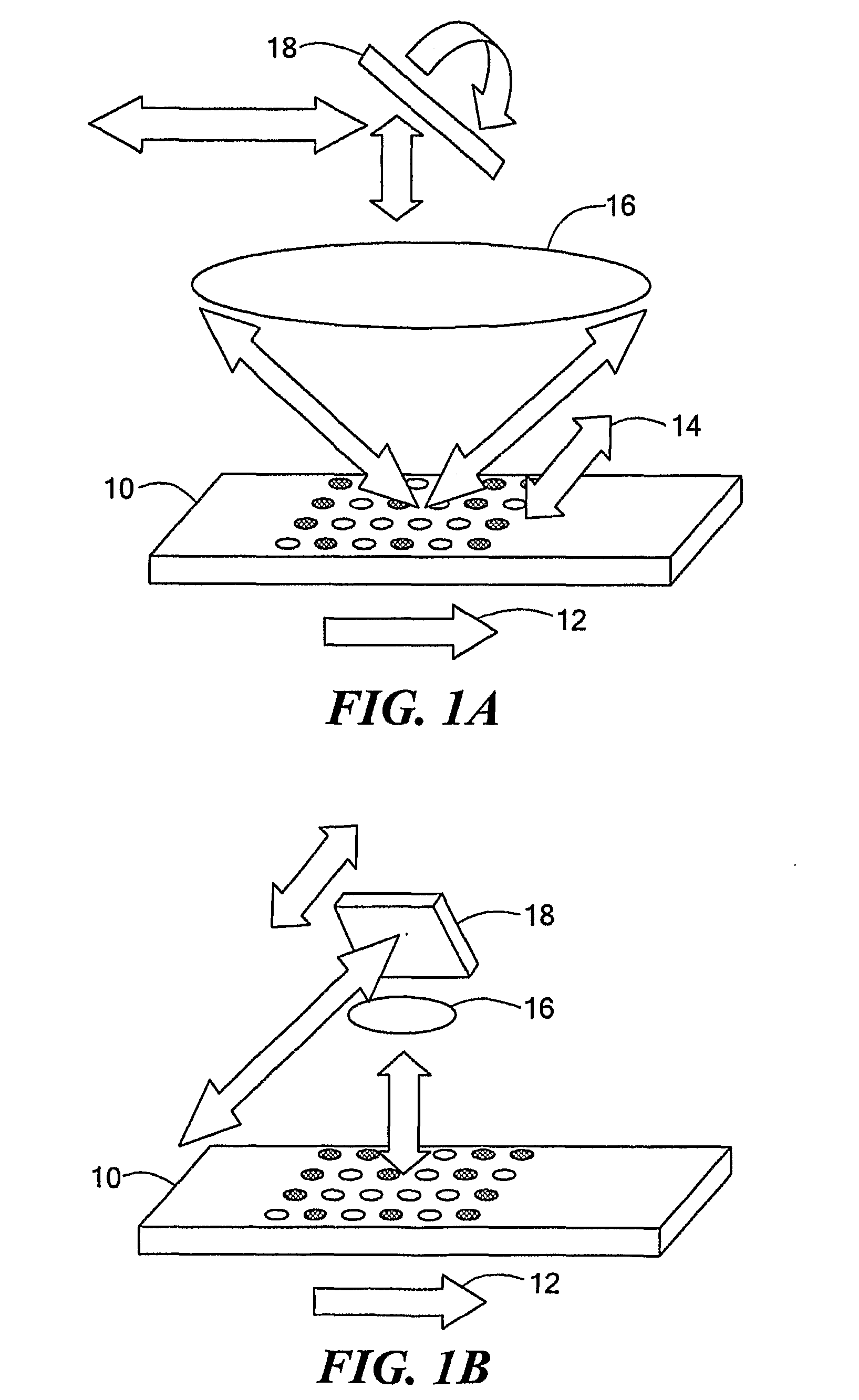
Viewing from the top surface allows access under all circumstances but is complicated by the necessary depth of focus of the optics (many millimeters) and by challenges of interrogating the microarray (for example, a droplet of liquid) through liquid.
By coming up underneath the plate and passing the light through a transparent base these shortcomings can be negated, however the problems previously described for viewing through a thickness (of a plain microscope slide) become apparent.
An issue common to both configurations is that the base of the microarray and the focal plane of the optics have to coincide throughout the scan to produce an optimal signal.
An alternative is to incorporate an active focusing mechanism in the scanner, tracking the height of the scanning beam over the plate to take care of the undulations in the base, and to focus on the target; however the auto-focus optics adds considerably to the cost of the scanner instrument.

Method used


Image

  • Fiber Optic Interrogated Microslide, Microslide Kits and Uses Thereof
  • Fiber Optic Interrogated Microslide, Microslide Kits and Uses Thereof
  • Fiber Optic Interrogated Microslide, Microslide Kits and Uses Thereof

Examples


example i

Microarray Analysis of Proteins

[0227]In this example, immunoglobulin (antibody) samples are analyzed for their binding affinity to a fluorescently labeled antigen. First, the immunoglobulin samples are diluted into a printing buffer at 0.1-0.5 μg / μl. Then, immunoglobulin samples are printed as a microarray onto an epoxy treated microslide using a split pen printing device. A blocking solution is then used to neutralize unreacted epoxy groups on the surface of the microslide. The processed microarrays are reacted with a solution containing a fluorescent labeled antigen, and allowed to incubate to achieve binding equilibrium. The microarray is then washed to remove unreacted fluorescent material. The microarray is imaged by placing it directly onto the faceplate of a CCD camera to produce an image of fluorescence on the microarray. The fluorescence data are then analyzed to evaluate the relative binding affinity of the immunoglobulins in the microarray for the antigen.

example ii

Microarray Analysis of DNA

[0228]This example illustrates the use of a microarray formed on a microslide of the invention to sequence a genomic DNA from a bacterium. A series of DNA samples containing fragments representative of the genomic DNA of a bacterium are diluted into a spotting solution. The DNA samples are printed as a microarray on the epoxy coated surface of a microslide substrate. Unreacted epoxy groups are blocked. The fluorescently labeled sample of bacterial genomic DNA for sequence analysis is hybridized to the samples in the microarray. Unbound label is washed away. The microslide is scanned in a laser scanning microarray reader, and the fluorescence at each spot in the microarray is determined, thereby allowing the determination of the nucleotide sequence of the sample to be determined in a computer.


PUM


Abstract

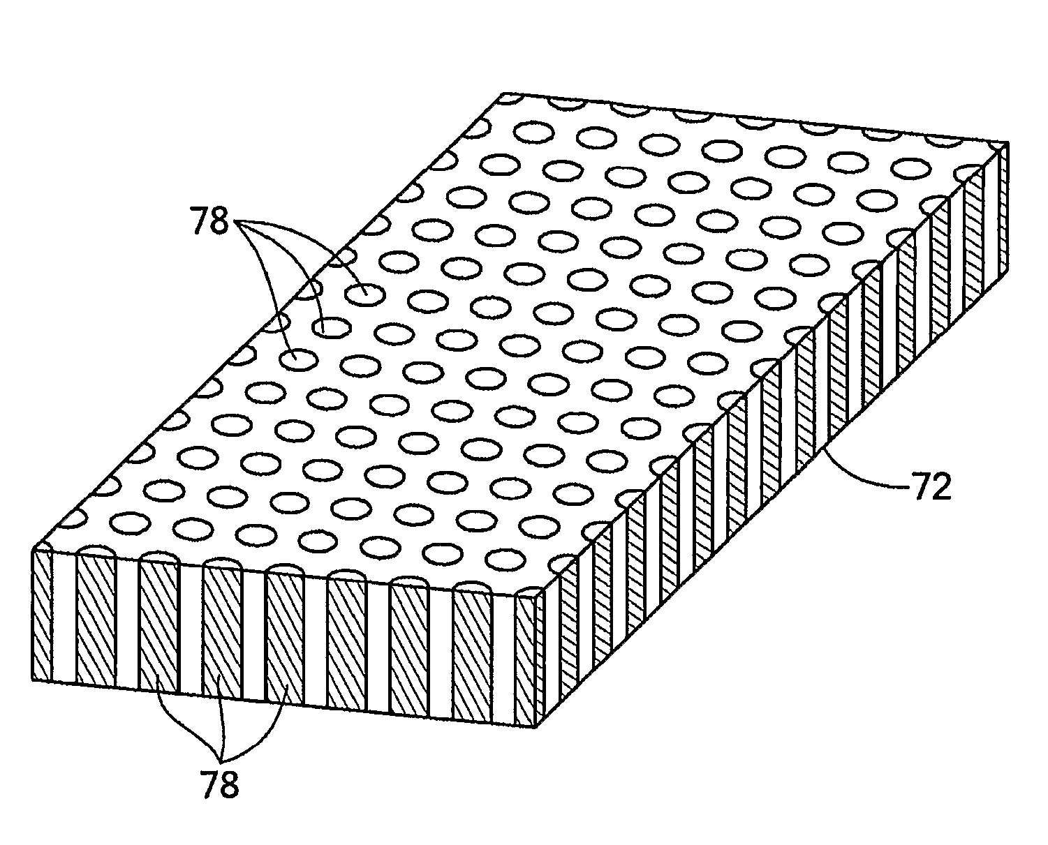
The present invention provides a substrate that overcomes the performance limitations of conventional microscope slides, microarrays, or microtiter plates when optically interrogated through the thickness of the substrate. With conventional microscope slides, image quality and resolution are degraded as a result of distortions introduced by imaging through the thickness of the glass. Fiber Optic Interrogated Microslides (FOI) consist of many fiber optics that have been fused together. When sliced and polished to form microscope slides, the fibers effectively transfer optical images from one surface of the microslide to the other. The finished microslide is the optical equivalent of a zero thickness window. The image of an object on the top surface is transferred to the bottom surface allowing it to be viewed without focusing through the thickness of the slide. In addition to providing improved image quality, FOI microslides allow objects to be directly imaged without complex and expensive focusing optics.

Description

RELATED APPLICATIONS[0001]This application claims the benefit of U.S. provisional application 60 / 734,597, filed Nov. 8, 2005. The entire content of that application is hereby incorporated by reference.FIELD OF THE INVENTION[0002]The invention relates to a FOI microslide which can be used as a substrate for a microarray, microtiter plate, or other applications such as those involving bottom reading.BACKGROUND OF THE INVENTION[0003]The first useful microscope was developed in the Netherlands between 1590 and 1608. For over 400 years of history, microscope slides, typically made of glass, have been used to support the object being studied. With conventional microscopy, a light source at the bottom of the microscope projects light up through a hole in the stage, through the microscope slide and the object being viewed (from above). In an inverted microscope, the light source and condenser are on the top above the stage pointing down. The objectives and turret are below the stage pointin...

Claims


Application Information

Patent Timeline
IPC IPC(8): G01N21/01B01J19/00C12M1/00G01N21/76C40B30/10C12Q1/70C12Q1/02
CPCG02B21/34G02B6/06
Inventor MINOT, MICHAEL J.STOWE, DAVID W.
Owner INCOM INC
Learn More