GMR configuration with enhanced spin filtering

a technology of enhanced spin filtering and mr sensor, which is applied in the field of mr sensor fabrication, can solve the problems of high output level of mr head in high-density magnetic recording, high sensitivity of mr sensor, etc., and achieve the effect of improving spin filtering

Inactive Publication Date: 2005-04-19
HEADWAY TECH INC
View PDF9 Cites 32 Cited by
  • Summary
  • Abstract
  • Description
  • Claims
  • Application Information

AI Technical Summary

Benefits of technology

[0014]It is an object of the present invention to provide a method for fa

Problems solved by technology

This leads to high sensitivity of the MR sensors and high out

Method used


Image

  • GMR configuration with enhanced spin filtering
  • GMR configuration with enhanced spin filtering
  • GMR configuration with enhanced spin filtering

Examples


first embodiment

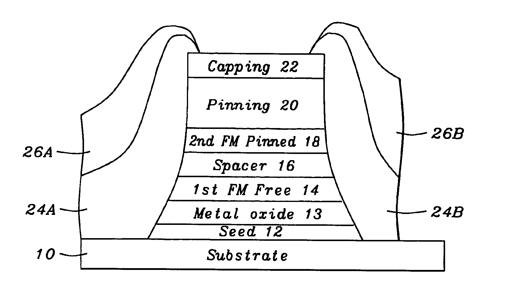
[0031]The GMR configuration of the invention, in the first embodiment, has an important buffer layer 13 composed of an metal oxide having a crystal lattice constant that is close the 1st FM free layer's 14 crystal lattice constant and has the same crystal structure (e.g., FCC, BCC, etc.). This metal oxide under layer 13 replaces the Ta conductor used in the inventor's previous process. The invention's metal oxide buffer layer 13 enhances the specular scattering. The invention's buffer layer 13 is comprised of oxides of metals that have a similar crystal lattice structure and constant to the adjacent FM layer 14.

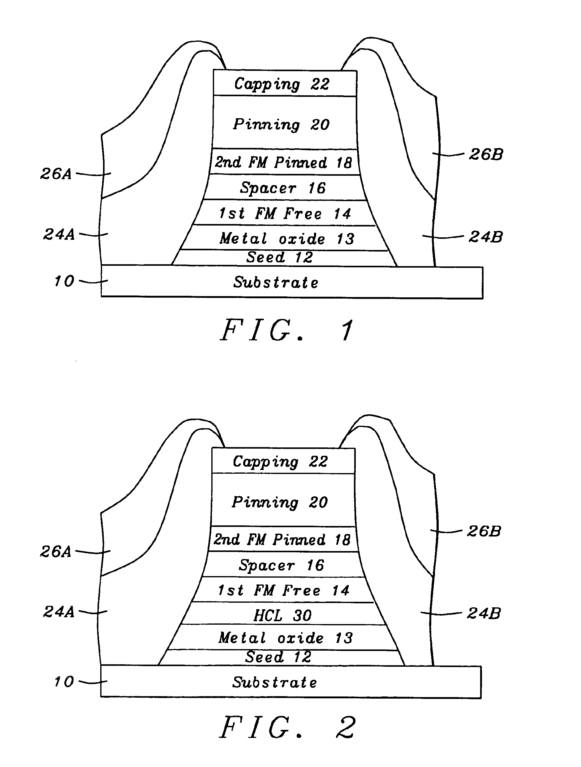
[0032]In the second embodiment (See FIG. 2), a high conductivity layer (HCL) 30 is formed over the buffer layer 13. The HCL layer enhances the GMR ratio of the spin filter SVGMR. See FIG. 4.

third embodiment

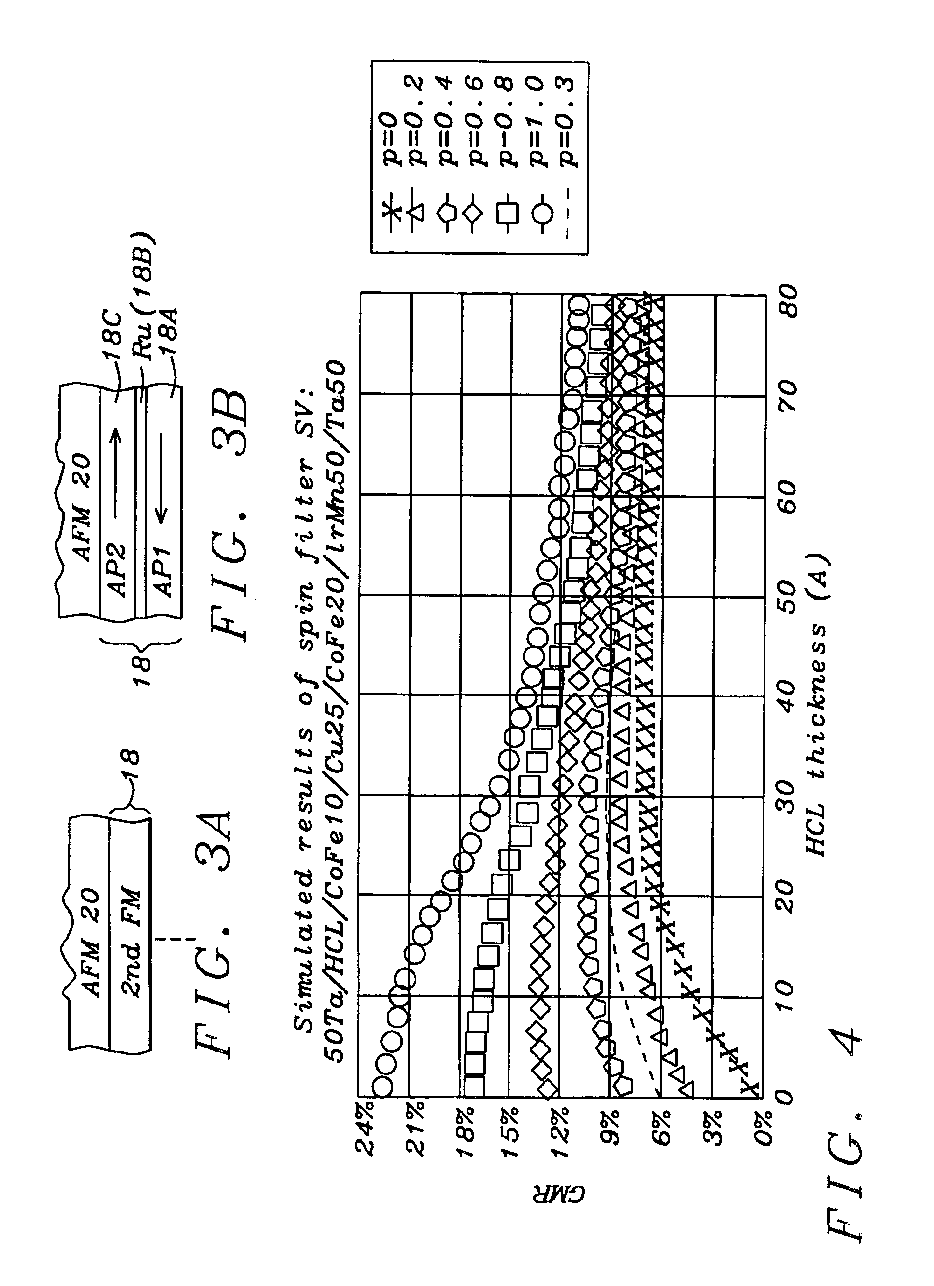
[0033]In the invention, the pinned ferromagnetic layer 18 (2nd FM pinned See FIG. 3A) is composed of a three layer structure comprising: (a) a lower AP1 layer (18A), a non-magnetic spacer (e.g., Ru) layer 18B and a upper AP layer (AP2 layer) 18C wherein the spacer layer 18B induces anti-ferromagnetic coupling between AP1 and AP2 which enhances the Pinning effect. The AP1 and AP2 layers have anti-parallel magnetic orientation. AP stands for anti-parallel.

[0034]A preferred first embodiment of the invention's spin valve giant magnetoresistance (SVGMR) sensor comprises: a substrate 10; a seed layer 12 over the substrate 10, the seed layer 12 being formed of a magnetoresistive resistivity sensitivity enhancing material selected from the group consisting of nickel chromium alloys, nickel-chromium-copper alloys and nickel-iron-chromium alloys; a metal oxide layer 13 (Buffer layer) over the seed layer; said metal oxide layer 13 comprised of NiO or alpha Fe2O3; a free ferromagnetic layer 14 ...

second embodiment

[0035]the invention is a Spin filter SVGMR that further includes: a high conductivity layer (HCL) 30 on said metal oxide layer 13 and said free ferromagnetic layer 14 on said high conductivity layer (HCL).

[0036]A third embodiment of the invention is a pinned FM layer comprised of a three layer structure of an lower AP layer, a spacer layer (e.g., Ru) and an upper AP layer.

[0037]The table below is a summary of the major element of the invention.

[0038]

TABLESummary of 1st and 2nd embodiments of the inventionPreferredLayerCharacteristicsPreferred MaterialsparametersCapping layer 22NiFeCr, NiCr, Ta(40 to 60 Å)Pinning layer 20MnPt, IrMn, MnNi, etc.pinned layer 18CoFe, Co20-30 Åspacer layer 16 -Cu20-30 Å,(non-magneticconductor)first free layer (FMpinned by ②CoFe, CoFe / NiFe, Co / NiFe.Ferromagnetic)buffer / AFM layerLayer 14High conductivitySpin valve SV hasCu, CuNi,10-30 Ålayer 30 (2ndHCL layer 30Embodiment -optional)**Invention's KeyMatches CrystalNiO, alpha-Fe2O3,buffer (metal oxide)lattice ...


PUM

PropertyMeasurementUnit
Currentaaaaaaaaaa
Currentaaaaaaaaaa
Currentaaaaaaaaaa

Abstract

Disclosed is a method of making a SVGMR sensor element. In the first embodiment a buffer layer is formed between a seed layer and a ferromagnetic (FM) free layer, the buffer layer being composed of alpha-Fe2O3 having a crystal lattice constant that is close to the FM free layer's crystal constant and has the same crystal structure. The metal oxide buffer layer enhances the specular scattering. In the second embodiment, a high conductivity layer (HCL) is formed over the buffer layer to create a spin filter-SVGMR. The HCL layer enhances the GMR ratio of the spin filter SVGMR. The third embodiment include a pinned FM layer comprising a three layer structure of a lower AP layer, a space layer (e.g., Ru) and an upper AP layer.

Description

[0001]This is a division of patent application Ser. No. 09 / 443,447, filing date Nov. 22, 1999 U.S. Pat. No. 6,770,382. A GMR Configuration With Enhanced in Filtering, assigned to the same assignee as the present invention, which is herein incorporated by reference in its entirety.BACKGROUND OF INVENTION[0002]1) Field of the Invention[0003]This invention relates generally to fabrication of magnetoresistive (MR) sensors employed within data storage and retrieval. More particularly, the present invention related to enhanced magnetoresistive (MR) spin valve filtering giant magnetoresistance (GMR) sensor elements.[0004]2) Description of the Prior Art[0005]In recent years, improvement in sensitivity of magnetic sensors and increase in density of magnetic recording are advancing. Concomitantly, development of magnetoresistance effect magnetic sensors (hereinafter abbreviated to MR sensors) and magnetoresistance effect magnetic heads (hereinafter abbreviated to MR heads) is making rapid pro...

Claims


Application Information

Patent Timeline
IPC IPC(8): G01R33/06G01R33/09H01F41/30G11B5/39H01F41/14G11B5/31H01F10/00H01F10/06H01F10/12H01F10/14H01F10/16H01F10/18H01F10/30H01F10/32H01L43/08H01L43/12
CPCB82Y10/00G01R33/093G11B5/3903G11B5/3909H01F10/30H01F10/3272H01L43/08B82Y25/00Y10T428/1171G11B5/3133Y10T428/1129Y10T428/12944Y10T428/1157Y10T428/1121Y10T428/2495H10N50/10
Inventor CHANG, JEI-WEIDIENY, BERNARDCHEN, MAO-MINHORNG, CHENG T.JU, KOCHANLIAO, SIMON
Owner HEADWAY TECH INC
Why Eureka
Try Eureka