Apparatus for and method of measuring surface shape of an object

a technology of surface shape and apparatus, applied in the direction of measuring devices, instruments, using optical means, etc., can solve the problems of phase discontinuity, more errors in measurement, and long measurement time, so as to improve the maneuverability of measurement, facilitate observation of the position and attitude of the measured object, and high speed

Inactive Publication Date: 2005-04-26
RICOH KK
View PDF9 Cites 21 Cited by
  • Summary
  • Abstract
  • Description
  • Claims
  • Application Information

AI Technical Summary

Benefits of technology

[0017]Yet another object of the present invention is to make the observation of the position and attitude of the measured object easy so as to improve the maneuverability of the measurement.
[0018]Yet another object of the present invention is to generate a depth-from-focus image at a high speed and to take more natural images of the measured object.
[0019]Yet another object of the present invention is to generate a more accurate depth-from-focus i

Problems solved by technology

However, if the object includes therein a step of more than ½ the wavelength, the step makes the unwrapping of the phase impossible and causes a phase discontinuity, and the result of the measurement consequently includes an uncertainty.
However, in the case where a user measures a large step with the scanning white light interferometer, the measurement takes a long time because the user must move either the object or the interferometer in the directions of the light axis.
Additionally, since the user must move the object or the interferometer during the measurement and measure the moving distance of the interferometer or the object, more error in measurement may be involved.
Accordingly, this technique can reduce the time required for measurement to some extent compared with the scanning white light interferometer, but it is considered that this technique cannot speed up the measurement beyond a certain limit.
This technique is not applicable to the measurement of dynamic change in shape of a moving object.
Additionally, the problem that the mechanical aspect

Method used


Image

  • Apparatus for and method of measuring surface shape of an object
  • Apparatus for and method of measuring surface shape of an object
  • Apparatus for and method of measuring surface shape of an object

Examples


Embodiment Construction

[0037]The preferred embodiments of the present invention will be described in detail below.

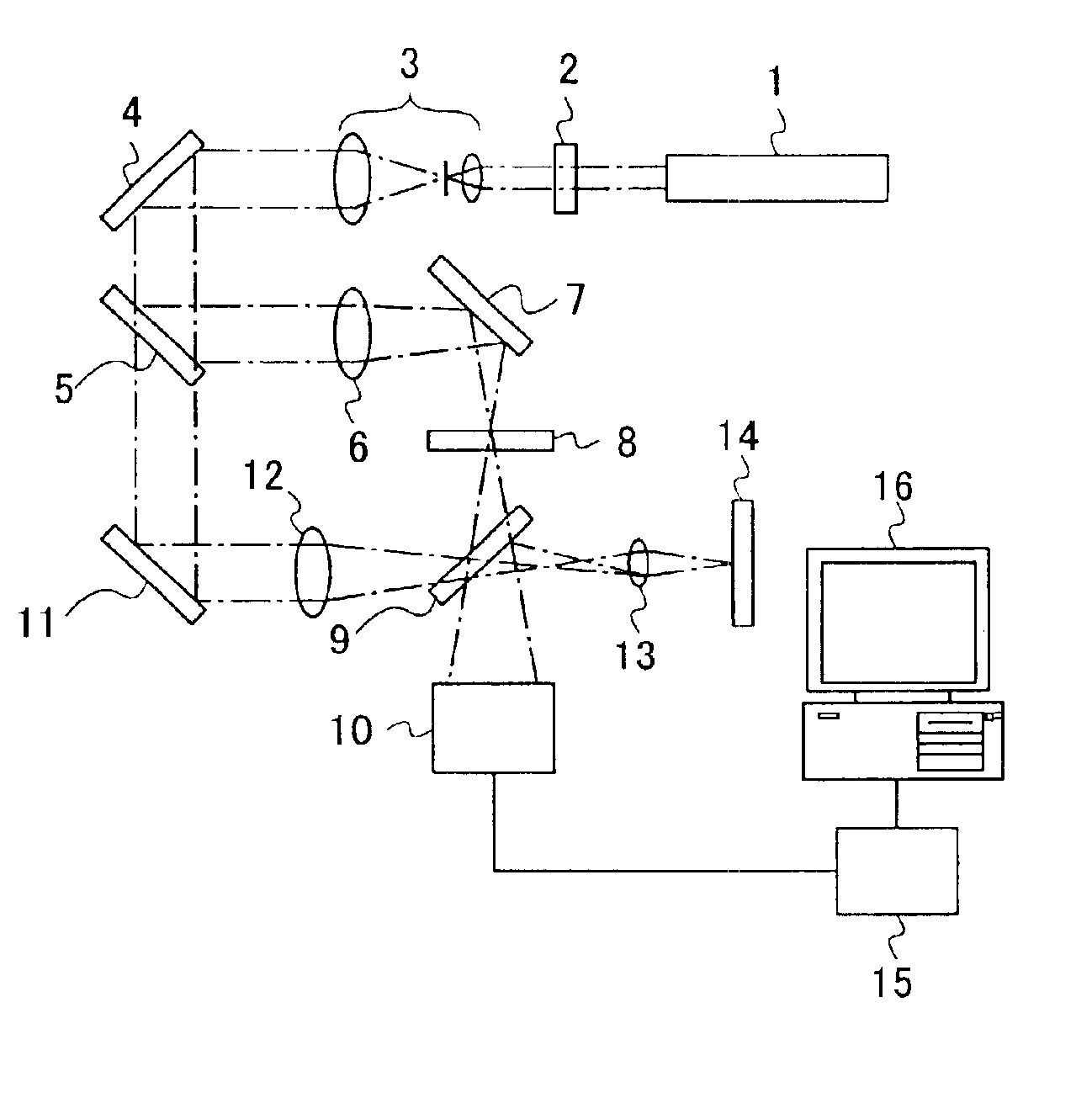
[0038]FIG. 1 is a block diagram showing the rough structure of an apparatus for measuring surface shape according to an embodiment of the present invention. As showed in FIG. 1, this apparatus for measuring surface shape includes a He—Ne laser 1 as a light source, an ND filter 2 for adjusting the intensity of the laser beam emitted by the He—Ne laser illuminating the measured object 14, and a beam expander 3 for expanding the laser beam. The beam expander 3 also functions as a spatial filter.

[0039]The beam expanded by the beam expander 3 is bent (reflected) by a mirror 4 and enters a beam splitter 5. The fraction of the beam reflected by the beam splitter 5 travels through a lens 6 for converting the beam into a spherical wave, is bent by a mirror 7, and enters an image device CCD 10 through an ND filter 8 and a half mirror 9. This fraction of the beam functions as a reference beam that interf...


PUM


Abstract

An apparatus for measuring an object's surface shape that obtains complex amplitude at a plurality of positions substantially in the directions of the optical axis of the light reflected by the object and calculates the first surface shape of the object by the depth-from-focus principle. On the other hand, using the phase data of the complex amplitude, the apparatus can measure a micro shape in the sub-fringe order by ordinary laser interference measurement. The first surface shape data are applied to a region including a step of a height greater than ½ of the light's wavelength and second surface shape data are applied to the other region.

Description

BACKGROUND OF THE INVENTION[0001]1. Field of the Invention[0002]The present invention generally relates to an apparatus for and a method of measuring the surface shape of an object, and more particularly, to the measurement of the surface shape of an object that includes a step of a height greater than ½ of the wavelength.[0003]2. Description of the Related Art[0004]A laser interferometer is known as an apparatus for measuring the surface form of an object in the range of the wavelength of light. For example, a laser interference system manufactured by Zygo Corp. is available in the market. The laser interferometer takes a plurality of interference fringe images using an imaging device such as a CCD with a reference beam of which phase is modulated, obtains the phase of reflected beam from the object based on the interference fringes, and obtains the shape of the object based on the phase data at the range of the wavelength of the reference beam.[0005]However, if the object includes...

Claims


Application Information

Patent Timeline
IPC IPC(8): G01B11/24
CPCG01B11/2441
Inventor MORITA, NOBUHIRO
Owner RICOH KK
Why Eureka
Try Eureka