Suppression of high frequency resonance in an electro-optical modulator

a high frequency resonance and modulator technology, applied in optics, instruments, optical light guides, etc., can solve the problems of reducing affecting the performance of the modulator, and requiring a large amount of data transfer bandwidth, so as to reduce the loss of insertion in the electro-optic device and suppress the modal coupling

Inactive Publication Date: 2005-04-26
LUMENTUM OPERATIONS LLC
View PDF5 Cites 4 Cited by
  • Summary
  • Abstract
  • Description
  • Claims
  • Application Information

AI Technical Summary

Benefits of technology

[0020]The method also includes interrupting a continuity of induced electrical current in the RF ground electrode. This substantially prohibits modal conversion and propagation of high order modes in the RF ground electrode and the plurality of electrically floating electrode segments. In one embodiment, the interrupting of the continuity of induced electrical current i

Problems solved by technology

For example, Internet video clips require a large amount of data transfer bandwidth.
However, such a structure may induce undesired longitudinal current in the ground electrodes that are electromagnetically coupled to the electrically floating electrodes.
This undesired longitudinal current can negatively impact the performance of the modulator.
For example, the undesired longitudinal current can result in couple

Method used


Image

  • Suppression of high frequency resonance in an electro-optical modulator
  • Suppression of high frequency resonance in an electro-optical modulator
  • Suppression of high frequency resonance in an electro-optical modulator

Examples


Embodiment Construction

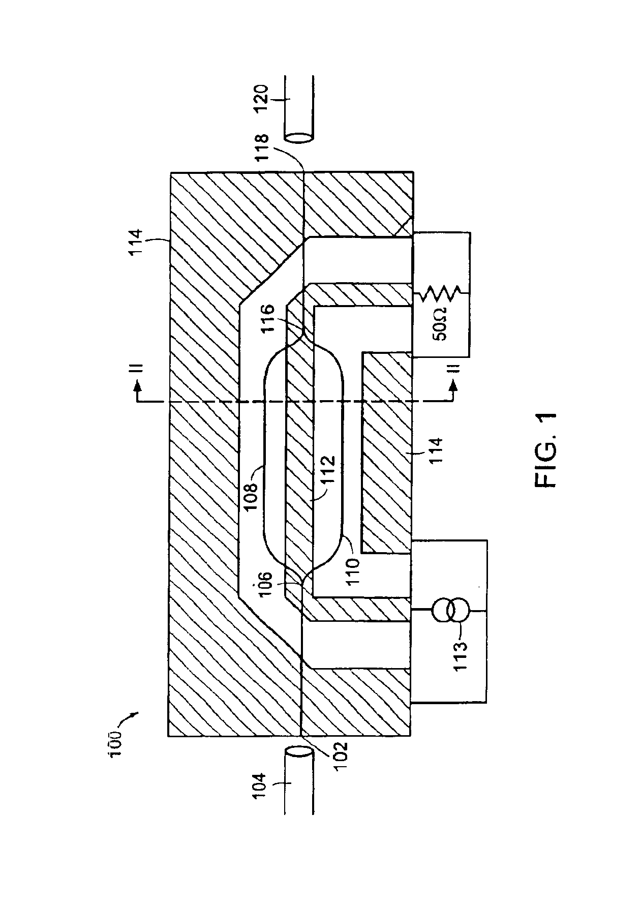
[0027]Referring to the drawings, FIG. 1 illustrates a top planar view of a floating electrode Mach-Zehnder interferometric (MZI) modulator 100 according to the present invention. Although the present invention is described herein with reference to a Mach-Zehnder modulator, the invention can be used with any type of electro-optical device. The modulator 100 includes an optical input 102 that is optically coupled to an optical waveguide, such as an input optical fiber 104. The input optical fiber 104 provides an incident optical signal from an optical source such as a laser diode (not shown).

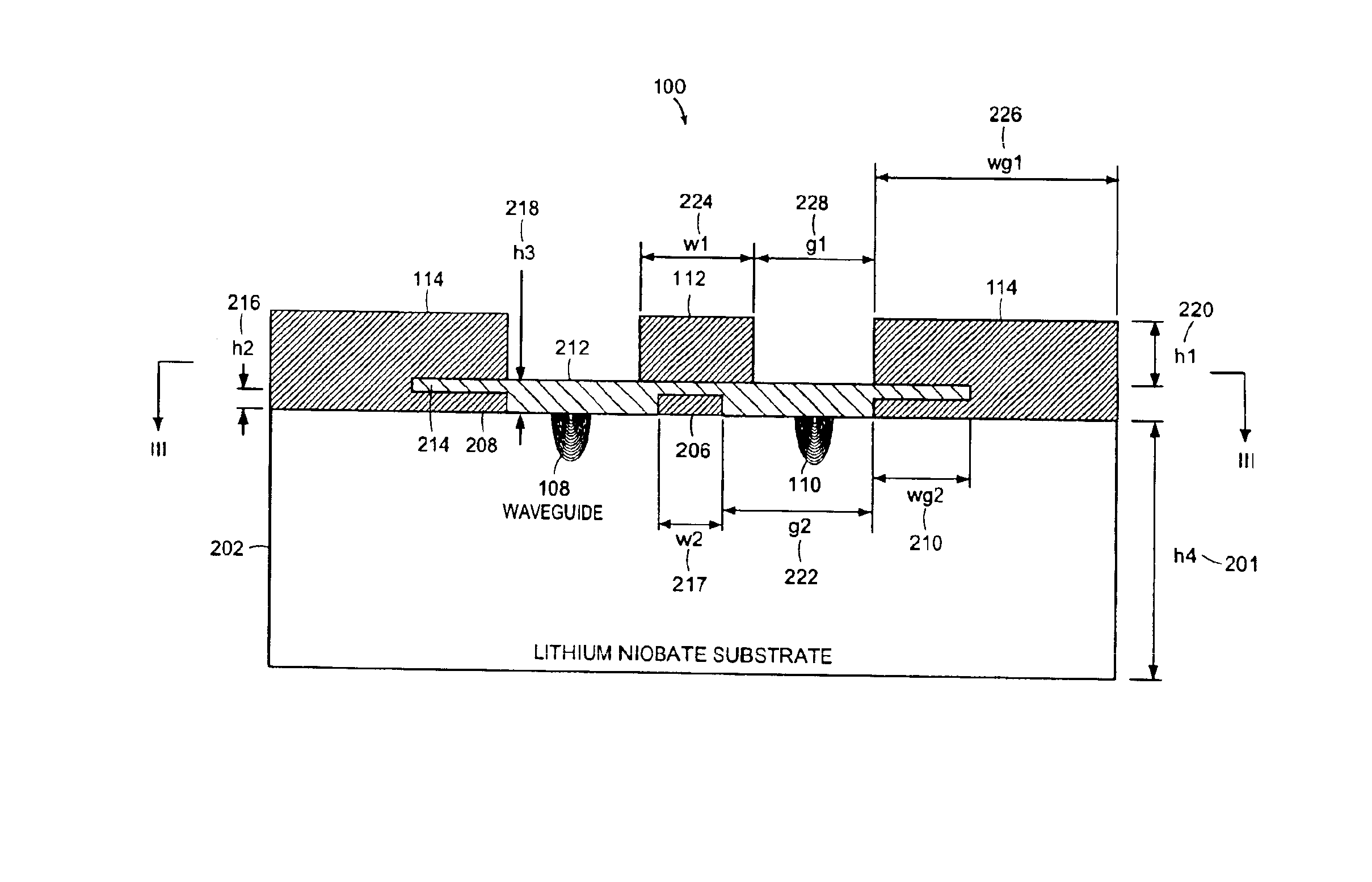
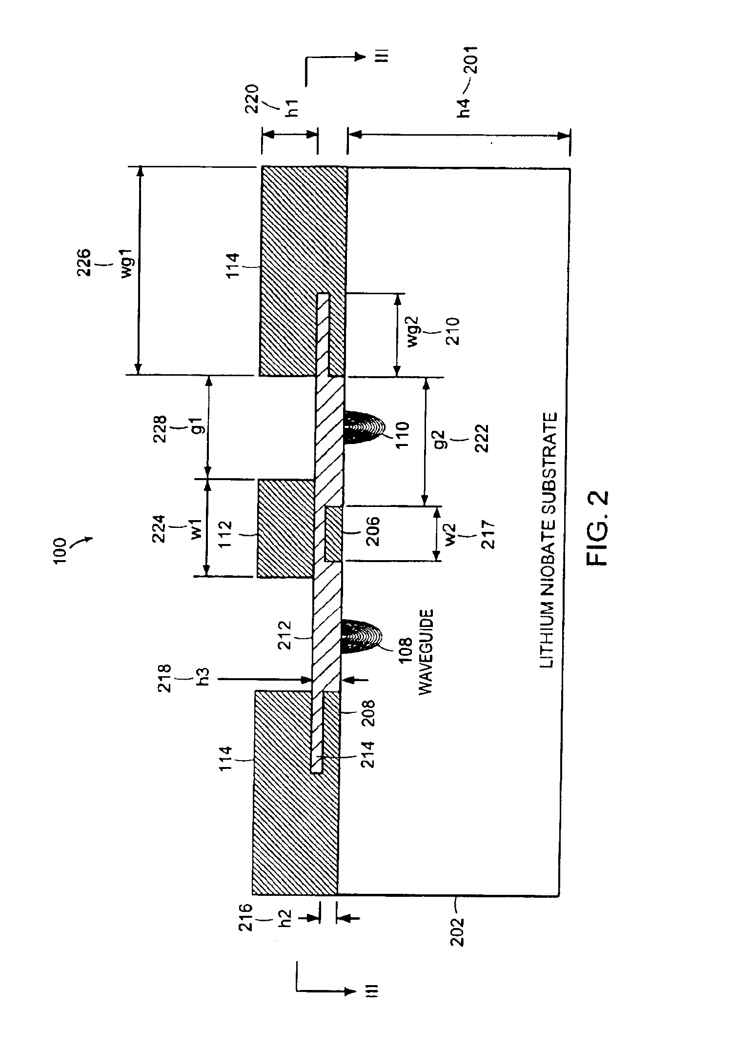
[0028]An optical splitter 106, such as a Y-junction, splits the incident optical signal into a first 108 and a second optical waveguide 110 that form a first and a second arm of the MZI modulator 100. In one embodiment, the optical waveguides 108, 110, each have a width of approximately seven (7) microns and are approximately three (3) microns thick. In one embodiment, the optical waveguides 108, ...


PUM


Abstract

The invention relates to suppression of high frequency resonance in an electro-optical device. The electro-optical device includes an optical waveguide formed in a substrate and a plurality of electrically floating electrode segments that are positioned on the substrate to intensify an electric field in the optical waveguide. The device also includes a RF ground electrode that is positioned on the substrate. The RF ground electrode defines a slot having a shape that suppresses modal conversion and propagation of high order modes in the RF ground electrode and in the plurality of electrically floating electrode segments, thereby suppressing modal coupling to the substrate. The device further includes a buffer layer formed on the upper surface of the substrate, on the plurality of electrically floating electrode segments, and in the slot. A driving electrode receives a RF signal that induces-the electric field in the optical waveguide.

Description

BACKGROUND OF INVENTION[0001]In the information age, the demand for data networks of higher and higher data capacities, at lower and lower costs is constantly increasing. This demand is fueled by many different factors, such as the tremendous growth of the Internet and the World Wide Web. The increasing number of on-line users of the Internet and the World Wide Web has greatly increased the demand for bandwidth. For example, Internet video clips require a large amount of data transfer bandwidth.[0002]Optical fiber transmission has played a key role in increasing the bandwidth of telecommunications networks. Optical fiber offers much higher bandwidths than copper cable and is less susceptible to various types of electromagnetic interferences and other undesirable effects. As a result, optical fiber is the preferred medium for transmission of data at high data rates and over long distances.[0003]In optical fiber communication systems, data is transmitted as light energy over optical f...

Claims


Application Information

Patent Timeline
IPC IPC(8): G02F1/035G02F1/01G02F1/225G02F1/21
CPCG02F1/0356G02F1/2255G02F2201/128G02F2001/212G02F1/212
Inventor CHEUNG, STEVEKISSA, KARLMCBRIEN, GREGORY J.
Owner LUMENTUM OPERATIONS LLC
Why Eureka
Try Eureka