
Segmented pallet for disk-shaped substrate electrical biassing and apparatus comprising same

a technology of electrical biasing and segmented pallets, which is applied in the direction of lighting and heating apparatus, charge manipulation, furniture, etc., can solve the problems of long chamber lengths, different bias potentials applied to the moving pallet, and the application of optimal substrate bias for particular films or layer deposition thereon

Inactive Publication Date: 2005-05-03
SEAGATE TECH LLC
View PDF24 Cites 18 Cited by
  • Summary
  • Abstract
  • Description
  • Claims
  • Application Information

AI Technical Summary

Benefits of technology

[0010]An advantage of the present invention is an improved pallet for transporting a plurality of workpieces / substrates through an apparatus adapted for performing at least one treatment of at least one surface of each of the workpieces / substrates.
[0011]Another advantage of the present invention is an improved pallet for selectively and controllably applying electrical bias potentials to selected pluralities of workpieces / substrates transported through an apparatus adapted for performing a plurality of treatments of at least one surface of each of the workpieces / substrates.
[0012]A further advantage of the present invention is an improved apparatus for performing a plurality of treatments of at least one surface of each of a plurality of workpieces / substrates.
[0013]A still further advantage of the present invention is an improved apparatus for performing a plurality of treatments of at least one surface of each of a plurality of workpieces / substrates, comprising an improved pallet for selectively and controllably applying electrical bias potentials to various pluralities of workpieces / substrates.
[0014]Yet another advantage of the present invention is an improved method of treating a plurality of substrates.
[0015]Still another advantage of the present invention is an improved method of treating a plurality of substrates, utilizing an in-line treatment apparatus comprising an improved pallet for selectively and controllably applying electrical bias potentials to various pluralities of workpieces / substrates.

Problems solved by technology

However, when the films or layers are deposited in a more cost-effective manner at high product throughput onto closely-packed pluralities of disk substrates carried by a moving pallet, i.e., an elongated, electrically conductive pallet, application of optimum substrate bias for particular film or layer deposition thereon may be problematic.
For example, and particularly where a plurality of different coating material sources, e.g., magnetron sputtering sources, are located in spaced adjacency within a single vacuum chamber of an in-line apparatus, application of different bias potentials to the moving pallet as the disks carried thereon pass by a particular cathode may be difficult, if not impossible, for the following reason: in such in-line apparatus, sliding electrical bias contactors are located on a single potential rail that contacts the bottom edge of the pallet as it passes through the chamber, maintaining the pallet at that bias potential for as long as the pallet remains in the process chamber.
However, such approach disadvantageously requires long chamber lengths, increased pumping capacity and system footprint or area, as well as substantially increased cost.
In either instance, separation of adjacent cathodes by a pallet length to provide optimum bias potentials is clearly impractical in terms of cost and system size, and the alternative of continuing to process pallets at less than optimum bias potentials is similarly unattractive, in that the attendant loss of media performance may be as high as several dB in SMNR.

Method used


Image

  • Segmented pallet for disk-shaped substrate electrical biassing and apparatus comprising same
  • Segmented pallet for disk-shaped substrate electrical biassing and apparatus comprising same
  • Segmented pallet for disk-shaped substrate electrical biassing and apparatus comprising same

Examples


Embodiment Construction

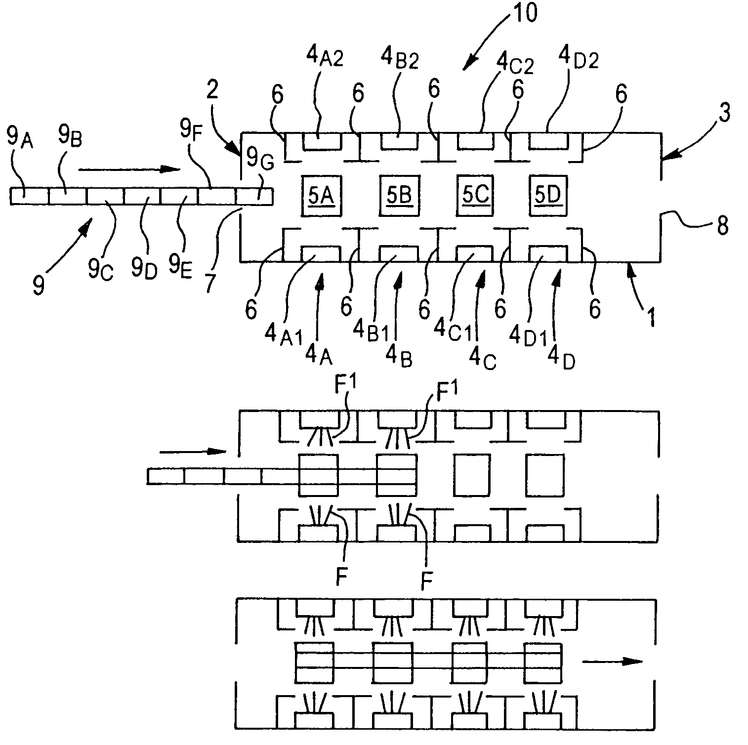
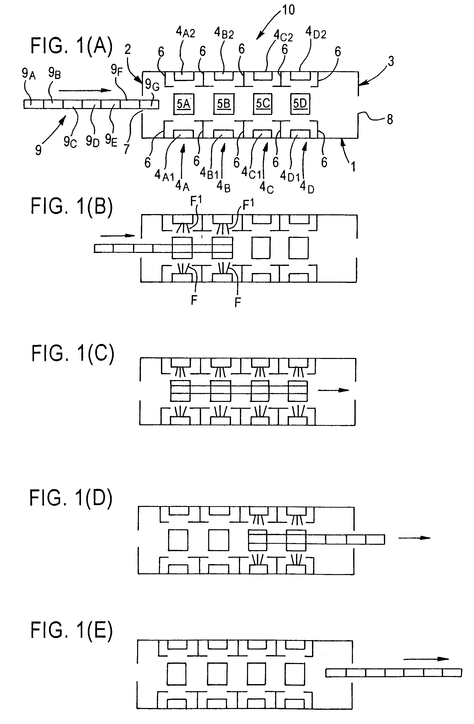
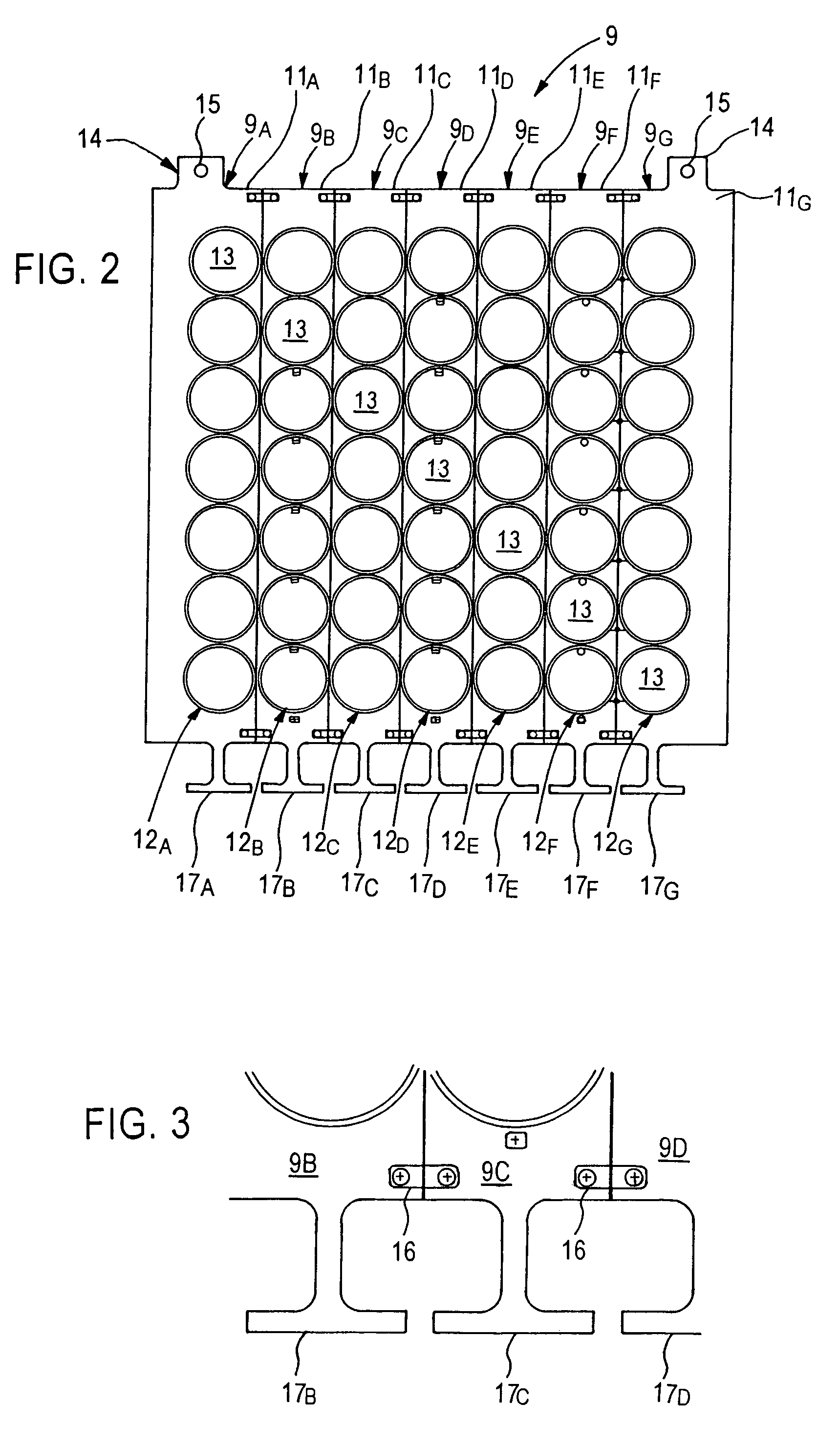
[0068]The present invention is based upon recognition by the inventor that the above-described limitations, disadvantages, and drawbacks imposed by the use of conventional in-line, multi-station processing apparatus comprised of a serially arranged plurality of different treatment stations in a single chamber, and elongated pallets for mounting and transporting a plurality of workpieces / substrates past the plurality of serially arranged treatment stations, wherein optimal treatment of the workpieces / substrates at each station requires application thereto of a pre-selected bias potential for that station, can be overcome by utilizing pallets comprised of a plurality of electrically insulated segments each comprised of an electrically conductive material, and providing each treatment station of the apparatus with a means for applying a pre-selected bias potential contact means which electrically contacts a segment of the pallet during the interval in which that segment is transported...


PUM

PropertyMeasurementUnit
electrically conductiveaaaaaaaaaa
electricallyaaaaaaaaaa
bias potentialaaaaaaaaaa

Abstract

An apparatus for performing treatments to the surface of disk-shaped workpieces / substrates, as in the manufacture of multi-layer, thin-film recording media. The apparatus includes treatment stations for performing treatments to a surface of each of the disk-shaped workpieces / substrates; a pallet adapted for mounting the disk-shaped workpieces / substrates, a plurality of bias potential sources; and a transporting source to transport the pallet past the treatment stations. The pallet includes electrically conductive segments and each segment is electrically insulated from other segments; is adapted to mount and expose at lest one surface of a disk-shaped workpiece; and includes an electrical contact for providing electrical contact with the bias potential source of the apparatus.

Description

CROSS-REFERENCE TO PROVISIONAL APPLICATION[0001]This application claims priority from U.S. provisional patent application Ser. No. 60 / 359,787, filed Feb. 25, 2002, the entire disclosure of which is incorporated herein by reference.FIELD OF THE INVENTION[0002]The present invention relates to an apparatus and method for simultaneously applying different electrical bias potentials to a plurality of workpieces / substrates carried by a moving pallet past a plurality of treating stations. The invention has particular utility in the automated manufacture of magnetic or magneto-optical recording media comprising a multi-layer stack of thin film layers formed on an insulative substrate, e.g., a disk-shaped substrate, by means of a physical vapor deposition (PVD) process, e.g., sputtering.BACKGROUND OF THE INVENTION[0003]Magnetic and MO media are widely employed in various applications, particularly in the computer industry for data / information storage and retrieval purposes. A magnetic medium...

Claims


Application Information

Patent Timeline
Patent Type & Authority Patents(United States)
IPC IPC(8): C23C14/56C23C14/50H01L21/00
CPCC23C14/50C23C14/568H01L21/67236Y10T29/49155Y10T29/49128Y10T29/53187Y10T29/53261Y10T29/53265Y10T29/532
Inventor MCLEOD, PAUL STEPHENKIM, TAESUN ERNEST
Owner SEAGATE TECH LLC
Learn More