Exterior building cladding having rigid foam layer with drain channels

a technology of foam layer and exterior cladding, which is applied in the direction of walls, building components, construction materials, etc., can solve the problems of condensation and subsequent corrosion along the connector, and the problem of condensation and corrosion may continue, so as to prevent the outside from cold and low conductivity

Inactive Publication Date: 2005-05-03
SCHILGER HERBERT K
View PDF10 Cites 70 Cited by
  • Summary
  • Abstract
  • Description
  • Claims
  • Application Information

AI Technical Summary

Benefits of technology

[0010]In a further embodiment the low conductivity connector may be in the form of a composite strip comprising a thin metal strip, e.g. galvanized sheet metal, with at least the portion of the metal strip that projects to the outside of the rigid foam insulation being encased with a layer of high density, closed cell plastic foam material. This provides added security against structural failure of connectors made entirely of plastic mate

Problems solved by technology

Particularly when a steel frame is used, when there is a difference between exterior and interior temperatures, there tends to be condensation and subsequent corrosion along the connector from the cold exterior cladding to the warm interio

Method used


Image

  • Exterior building cladding having rigid foam layer with drain channels
  • Exterior building cladding having rigid foam layer with drain channels
  • Exterior building cladding having rigid foam layer with drain channels

Examples


Embodiment Construction

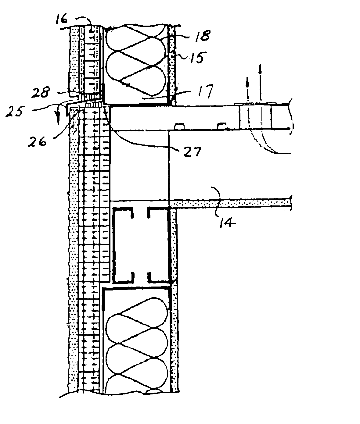
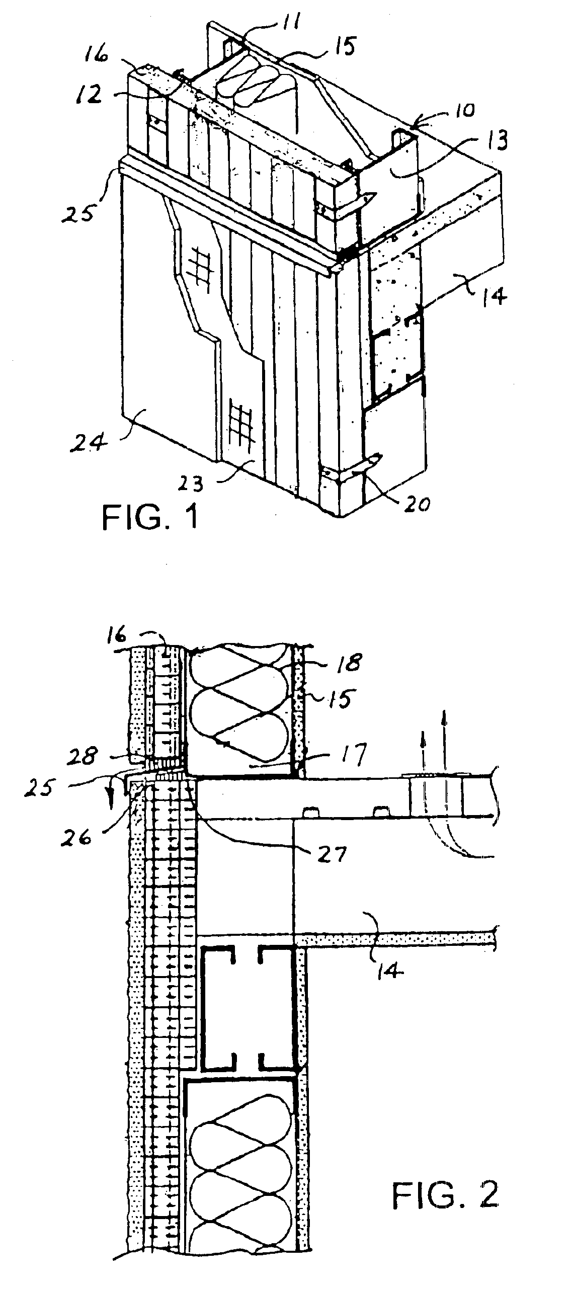
[0025]As seen in FIGS. 1 and 2, this construction according to the present invention includes an interior framework formed of steel studs 10. Each stud has an inner flange 11, an outer flange 12 and a central web 13. Floor beams 14 intersect the wall frame portions.

[0026]A standard wall paneling 15 is connected to inner flanges 11 of studs 10 and panels of rigid foam insulation 16 are placed adjacent the outer face of the outer flange 12 of studs 10. The inner wall panels and the foam panels form therebetween the wall cavity 17 that is fill with commercial insulation 18, e.g. glass fiber batts.

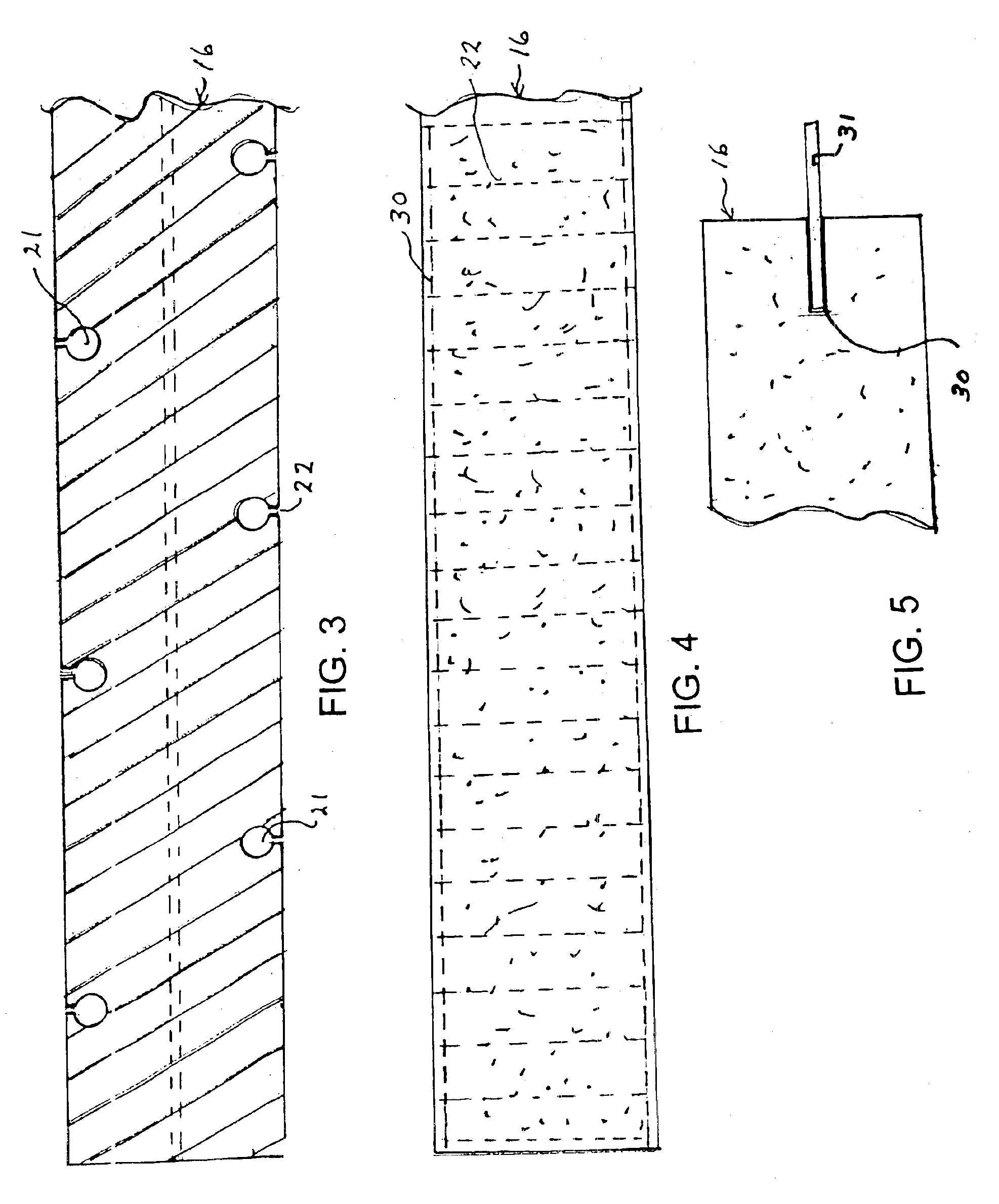
[0027]The rigid foam panels 16 are connected to the studs 10 by way of plastic connectors 20 one type of which can be seen in FIG. 1. In the particular embodiment of FIGS. 1 and 2, a metal mesh stucco lath 23 is applied over the rigid foam panels 16 and over the lath is applied an exterior stucco coating 24.

[0028]The wall structures are horizontally separated at each floor level of a structure...


PUM

PropertyMeasurementUnit
Thicknessaaaaaaaaaa
Distanceaaaaaaaaaa
Electrical conductivityaaaaaaaaaa

Abstract

A novel building construction is described for exterior building walls. The construction comprises an interior frame formed of a plurality of laterally spaced studs or beams, a layer of rigid insulation adjacent to the exterior side of this steel frame, exterior building cladding adjacent the exterior side of the rigid insulation and a plurality of low conductivity connectors, e.g. insulating plastic connectors or thin metal strips having an insulating plastic foam coating, extending through the layer of rigid insulation and connecting together the exterior cladding and the interior steel studs or beams. Vertical channels are formed adjacent both the inside and outside faces of the insulation layer to remove moisture. This provides the required structural strength with a minimum of thermal conductivity from the warm side to the cold side of the building envelope, while providing exterior drain channels and interior moisture removing channels.

Description

CROSS-REFERENCE TO RELATED APPLICATION[0001]This application is a continuation-in-part of application Ser. No. 10 / 411,305, filed Apr. 11, 2003.BACKGROUND OF THE INVENTION[0002]This invention relates to building construction and more particularly to a building wall construction having an interior frame work and exterior cladding.[0003]Particularly in colder climates, it has been a common building technique for many years to construct an interior support frame, with an exterior wall cladding or shell fixed to the exterior side of the frame and an interior wall fixed to the interior side of the frame. Many different materials have been used for the exterior wall cladding, including brick veneer, aluminum siding, vinyl siding, wood siding, stucco, concrete, glass, metal, etc. Such constructions may be made with or without insulating materials.[0004]The frame is typically made of wood or steel and frames made of steel studs and beams are now becoming more commonplace even for home constr...

Claims


Application Information

Patent Timeline
IPC IPC(8): E04C2/10E04C2/20
CPCE04C2/205
Inventor SCHILGER, HERBERT K.
Owner SCHILGER HERBERT K
Why Eureka
Try Eureka