Prosthetic implant having segmented flexible stem

a flexible stem and prosthetic technology, applied in the field of prosthetic implants having a fixation stem, can solve the problems of provoking tissue reactions, one or both of the articulation surfaces of the hip joint may not perform properly, and the overall structure is stiff, so as to reduce or vary the stiffness, and reduce the mechanical stiffness of the stem

Inactive Publication Date: 2005-05-03
MAYO FOUND FOR MEDICAL EDUCATION & RES
View PDF39 Cites 28 Cited by
  • Summary
  • Abstract
  • Description
  • Claims
  • Application Information

AI Technical Summary

Benefits of technology

[0020]It is therefore an advantage of the present invention to provide a prosthetic implant having a fixation stem with reduced or varying stiffness such that the stress shielding problems associated with the high mechanical stiffness of the stem can be minimized.
[0021]It is another advantage of the present invention to provide a prosthetic implant having a fixation stem with reduced or varying stiffness wherein the implant transmits loads to the surrounding support bone in a more optimum manner such that stress shielding in minimized.
[0022]It

Problems solved by technology

One or both of the articulation surfaces of the hip joint may fail to perform properly, requiring the defective natural articulation surface to be replaced with a prosthetic articulation surface.
While bone cements provide the initial fixation necessary for healing following surgery, bone cements often result in a very stiff overall structure, are prone to loosening with time, and can provoke tissue reactions.
Because of the disadvantages associated with the use of bone cements, “cementless” or “press fit” femoral implants have been developed.
A recognized problem with the use of an interference fit (press-fit) femoral implant stem is that transfer of stress from the femoral implant to the femur is abnormal.
This leads to weakening over a period of years, thus creating a potential for fracture or a loosening of the femoral implant within the femur.
It has been reported that one cause of stress sh

Method used


Image

  • Prosthetic implant having segmented flexible stem
  • Prosthetic implant having segmented flexible stem
  • Prosthetic implant having segmented flexible stem

Examples


Embodiment Construction

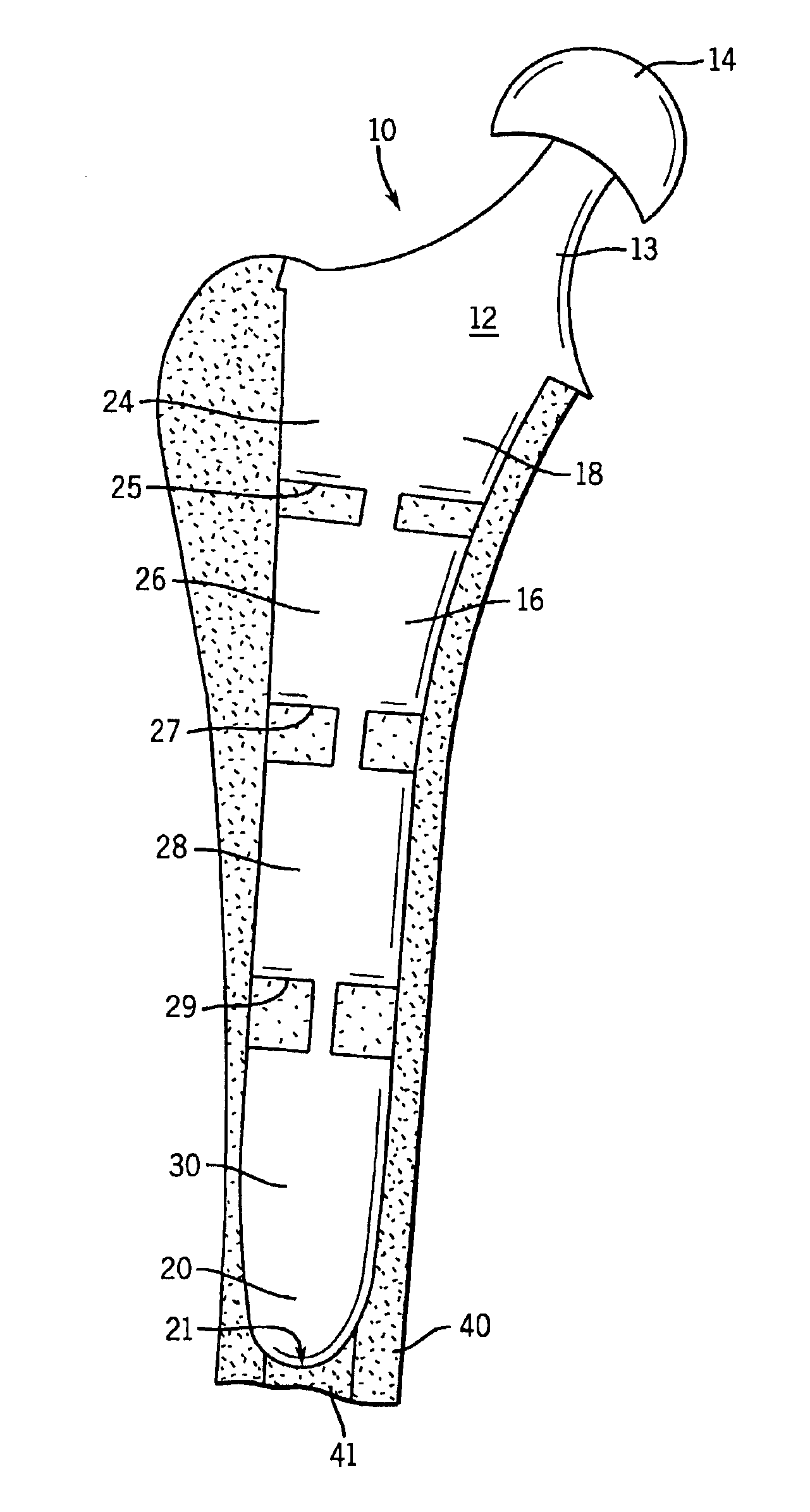
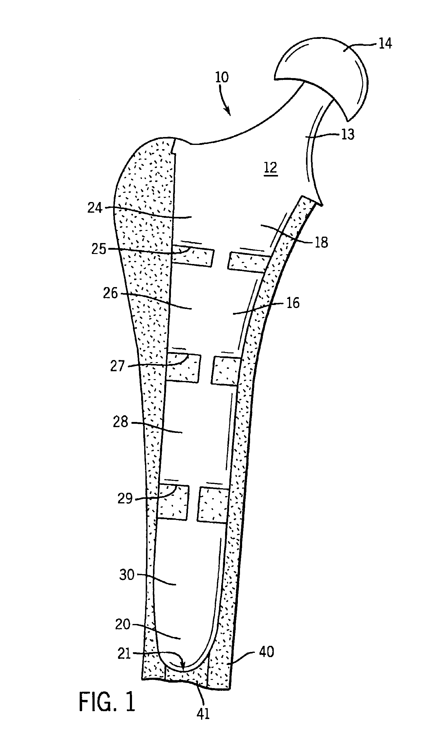
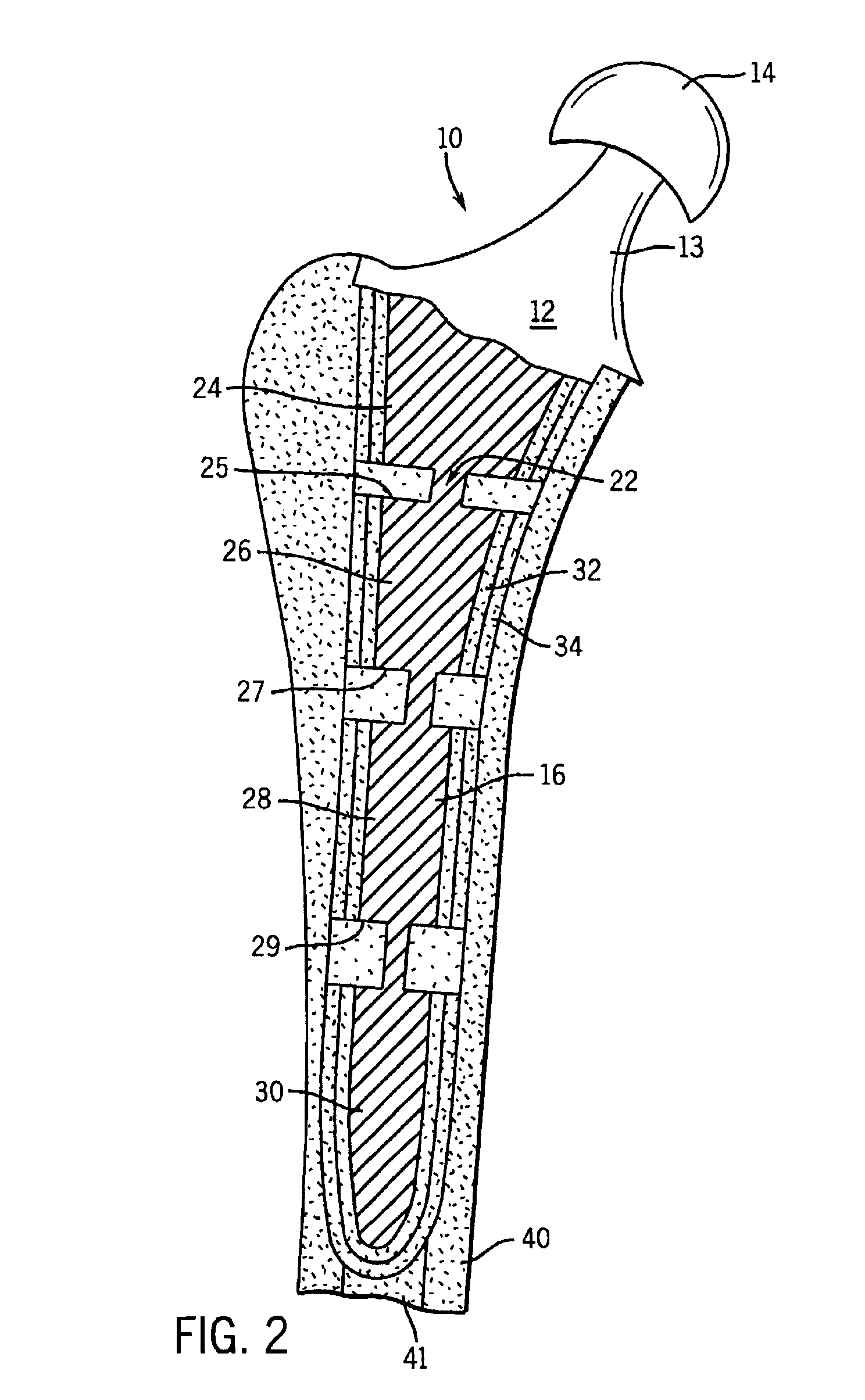
[0029]The present invention is directed to a flexible prosthesis for implanting into a bone having a cavity. The prosthesis illustrated and described herein is a femoral prosthesis component of an artificial hip joint in which the femoral prosthesis is implanted in the femoral medullary canal. However, it should be understood that the methods and prostheses according to the invention can be used in the repair of any bone or in connection with the implantation of prosthetic devices in any bone in the body, adjacent to or remote from any joint, including without limitation the hip, knee and spinal joints. Further, the methods and prostheses according to the invention can be used in primary surgery, in which a prosthesis is being used to reconstruct a joint for the first time, as well as in revision surgery in which a previously-implanted prosthesis is being replaced with another prosthesis. Press fit, cement or other fixation techniques can be employed in conjunction with the methods ...


PUM

PropertyMeasurementUnit
Lengthaaaaaaaaaa
Sizeaaaaaaaaaa

Abstract

A prosthetic implant having a fixation stem with varying stiffness is disclosed. The stem comprises an elongated core and segments extending outward from the core. The segments are spaced apart so as to define transverse grooves surrounding the core between adjacent segments. The longitudinal length of the grooves, and the materials used for the core and the segments are selected such that the stiffness of the stem varies from the proximal end to the distal end. Typically, the stiffness of the stem will be lower at the distal end such that the distal end of the stem bears less force when loaded and thereby transfers more load to the proximal end of the stem, which has a higher stiffness. As a result, stress shielding, in which the load bypasses the proximal end of the stem, is minimized and bone resorption adjacent the proximal end of the stem is decreased.

Description

CROSS-REFERENCE TO RELATED APPLICATIONS[0001]Not Applicable.STATEMENT REGARDING FEDERALLY SPONSORED RESEARCH[0002]Not Applicable.BACKGROUND OF THE INVENTION[0003]1. Field of the Invention[0004]This invention relates to prosthetic implants having a fixation stem, and in particular relates to a prosthetic implant having a fixation stem with decreased or varying stiffness such that the problems associated with stress shielding are reduced.[0005]2. Description of the Related Art[0006]For many years now, prostheses have been implanted in the human body to repair or reconstruct all or part of an articulating skeletal joint, such as the hip joint. The hip joint includes the femur and the pelvis, each of which has a surface for articulation against an adjacent articulation surface of the other bone. The femur has a head having a convex, generally spherically contoured articulation surface. The pelvis includes an acetabulum having a concave, generally spherically contoured articulation surfa...

Claims


Application Information

Patent Timeline
IPC IPC(8): A61F2/32A61F2/00A61F2/30A61F2/36
CPCA61F2/30767A61F2/3662A61F2310/00976A61F2/30965A61F2/36A61F2/367A61F2/3676A61F2002/30014A61F2002/30113A61F2002/30224A61F2002/30324A61F2002/30326A61F2002/30733A61F2002/30822A61F2002/30827A61F2002/30828A61F2002/30929A61F2002/3611A61F2002/3631A61F2230/0006A61F2230/0069A61F2250/0018A61F2250/0036A61F2250/0037A61F2310/00017A61F2310/00023A61F2310/00029A61F2310/00131A61F2310/00203A61F2310/00239A61F2310/00401A61F2310/00407A61F2310/00413A61F2310/00544A61F2310/00796A61F2/30771
Inventor LEWALLEN, DAVID G.
Owner MAYO FOUND FOR MEDICAL EDUCATION & RES
Why Eureka
Try Eureka