Frequency-shifted feedback cavity used as a phased array antenna controller and carrier interference multiple access spread-spectrum transmitter

a frequency-shifted feedback cavity and antenna controller technology, applied in pulse techniques, instruments, and using reradiation, etc., can solve the problems of large scale, complex process, and difficult implementation of adaptive array deployment, and achieve the effect of easy adaptation

Inactive Publication Date: 2005-05-03
DEPARTMENT 13 INC
View PDF20 Cites 34 Cited by
  • Summary
  • Abstract
  • Description
  • Claims
  • Application Information

AI Technical Summary

Benefits of technology

[0019]Still another objective is to provide a spread-spectrum format that is easily adapted to adaptive array processing in a multiple-access communications system.

Problems solved by technology

These methods are complex processes and are more difficult to implement than the tracking of users in non-CDMA systems.
These changes may be the major obstacle for adaptive array deployment in the near future.
However, phase-based electronically controlled phased array systems are relatively large, heavy, complex, and expensive.
This arrangement results in a system that is relatively lossy, electromagnetically sensitive, hardware-intensive, and has a narrow tunable bandwidth.
However they increase system complexity and size by introducing complex elements and systems as well as by introducing additional detectors.
Several optical systems that exhibit unusual properties have been built, but their application to phased array signal processing had been overlooked.
Although pulse-radio systems are well known in the art, they are not well suited for commercial applications.
However, its broad bandwidth, particularly the portion occupying the low-frequency ranges of the RF spectrum, makes proposed commercial pulse-radio systems unlikely candidates for FCC approval.
The short pulse width of pulse-radio signals makes Rake reception very difficult.

Method used


Image

  • Frequency-shifted feedback cavity used as a phased array antenna controller and carrier interference multiple access spread-spectrum transmitter
  • Frequency-shifted feedback cavity used as a phased array antenna controller and carrier interference multiple access spread-spectrum transmitter
  • Frequency-shifted feedback cavity used as a phased array antenna controller and carrier interference multiple access spread-spectrum transmitter

Examples


Embodiment Construction

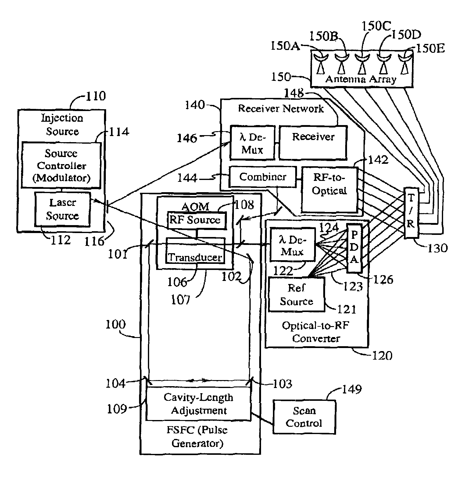
[0047]The standard method for sustaining laser oscillation uses feedback from a Fabry-Perot cavity. The multiple reflections within the cavity lead to destructive interference for all frequencies of light except those discreet frequencies that correspond to the standing waves of the cavity. This is demonstrated by frequency discrimination that occurs within an etalon. The intensity of light that is transmitted through an etalon is sharply peaked at the resonance of the cavity. Non-resonant waves destructively interfere within the cavity, thus canceling almost entirely. Therefore, a Fabry-Perot cavity used as a feedback cavity in a laser causes the laser output power to be distributed in a narrow spectral region that corresponds to the modes of the cavity.

[0048]A traveling-wave FSFC laser, as described in the cited papers co-authored by applicant, does not selectively attenuate frequencies. Rather, this laser is characterized by its unusually broad spectral output, which has no mode ...


PUM


Abstract

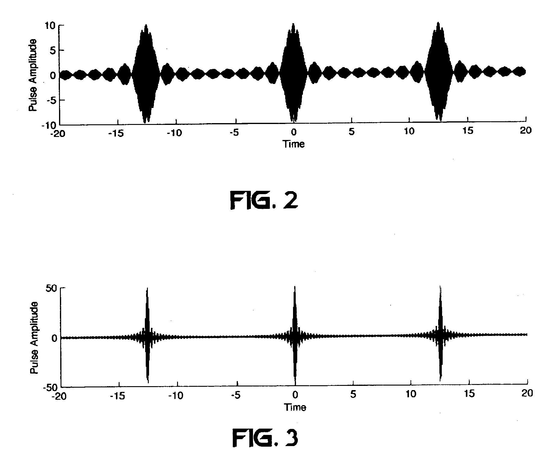
An optical processor for controlling a phased antenna array uses a frequency-shifted feedback cavity (FSFC), which includes a traveling-wave cavity. The FSFC incrementally delays and incrementally frequency shifts optical signals circulating in the traveling-wave cavity. Optical signals coupled out of the FSFC are separated by frequency, hence by delay, and processed to control either or both transmit and receive beam-forming operations. The FSFC provides a receiver with multiple receive signals which have incremental values of frequency. Each frequency corresponds to an incremental time sampling of optical signals input into the FSFC. Transmit signals coupled out of the FSFC have frequency and phase relationships that result in short time-domain pulses when combined. Controlling modulation and frequency of the transmit signals achieves carrier interference multiple access, a new type of spread-spectrum communications.

Description

[0001]This is a division of Ser. No. 09 / 022,950, now U.S. Pat. No. 5,955,992, Filed Feb. 12, 1998.BACKGROUND OF THE INVENTION[0002]I. Field of the Invention[0003]The present invention relates to wireless communication and radar systems. More specifically, the present invention relates to a novel and improved antenna array processor that controls beam-forming and scanning operations and that also introduces a new spread spectrum technique.[0004]II. Description of the Related Art[0005]Multiple access communication techniques include time-division multiple access (TDMA), frequency division multiple access (FDMA), amplitude modulation, and spread spectrum. Spread spectrum techniques provide some improvements over the other multiple access techniques depending on the type of spread spectrum used. Spread spectrum techniques are based on the principle of expanding a transmitted baseband signal in frequency. This achieves superior interference-rejection by utilizing high process gain to red...

Claims


Application Information

Patent Timeline
Patent Type & Authority Patents(United States)
IPC IPC(8): H04L27/26H04L1/04H04L1/02H04B1/7115H04B1/717G01S13/28H04J13/00
CPCH04B1/7174H04B7/0697H04B7/12H04J13/0077H04L27/2697H04J14/0298H04L1/04H04L27/2637H04L5/0021H04J14/02H04B1/7115
Inventor SHATTIL, STEVE J.
Owner DEPARTMENT 13 INC
Why Eureka
Try Eureka