Fusion-welding of defective components to preclude expulsion of contaminants through the weld

a technology of defective components and fusion welding, which is applied in the direction of solventing equipment, manufacturing tools, other domestic objects, etc., can solve the problems of subsequent crack closure and sealing, further disturbance of the weld pool, etc., and achieves increased weld penetration and heat input. high, the effect of increasing the heat inpu

Inactive Publication Date: 2005-05-10
GENERAL ELECTRIC CO
View PDF34 Cites 22 Cited by
  • Summary
  • Abstract
  • Description
  • Claims
  • Application Information

AI Technical Summary

Benefits of technology

[0006]For a given type of welding torch, process parameters and substrate material, this balance is not a constant but is a function of the torch travel speed, even though travel speed is already taken into account in the calculation of the “normalized” heat input (heat input per unit length of weld). Even though high heat input is well known to lead to increased weld penetration, and even though, in a preferred embodiment, the sealing weld does not penetrate beyond the depth of the closed portion (sealed ligament) of the crack, the most effective combination of welding parameters is higher heat input and a faster travel speed of the welding torch. The higher heat input enables the trapped contaminants to be more fully evaporated for displacement beyond or mixing within the weld pool, while the faster travel speed prevents penetration to an extent greater than the closed crack depth (sealed ligament). Also, since original unclosed cracks are not oriented perpendicular to the weld surface, they may interfere with normal heat transfer in the depth direction, causing a further disturbance of the weld pool. Deforming the cracks until tightly closed to a selected depth affords the benefit of a more continuous thermal path and weld penetration uniformity.
[0007]Remote excavation of a portion of the cracked depth enables subsequent weld repair to be made such that the structural margin of the component may be regained, while keeping excavation time and welding time to a minimum. An EDM (electrical discharge machining) process may be used as well as an alternative excavation process. That process, however, sometimes leave particles of removed material (known as dross or swarf) in the crack remnant, making subsequent crack closure and sealing difficult. The present preferred embodiment incorporates a fluid or gas jet nozzle directed at the work surface so that a gas or liquid can be used to clean at least the nearest surface portion of the crack of contaminants. If the jet flow is aggressive, such as a high-pressure water jet, it is also useful to remove oxides from the crack surfaces as we

Problems solved by technology

Also, since original unclosed cracks are not oriented perpendicular to the weld surface, they may interfere with normal heat transfer in the depth direction, causing a further disturbance

Method used


Image

  • Fusion-welding of defective components to preclude expulsion of contaminants through the weld
  • Fusion-welding of defective components to preclude expulsion of contaminants through the weld
  • Fusion-welding of defective components to preclude expulsion of contaminants through the weld

Examples


Embodiment Construction

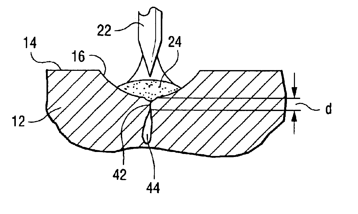
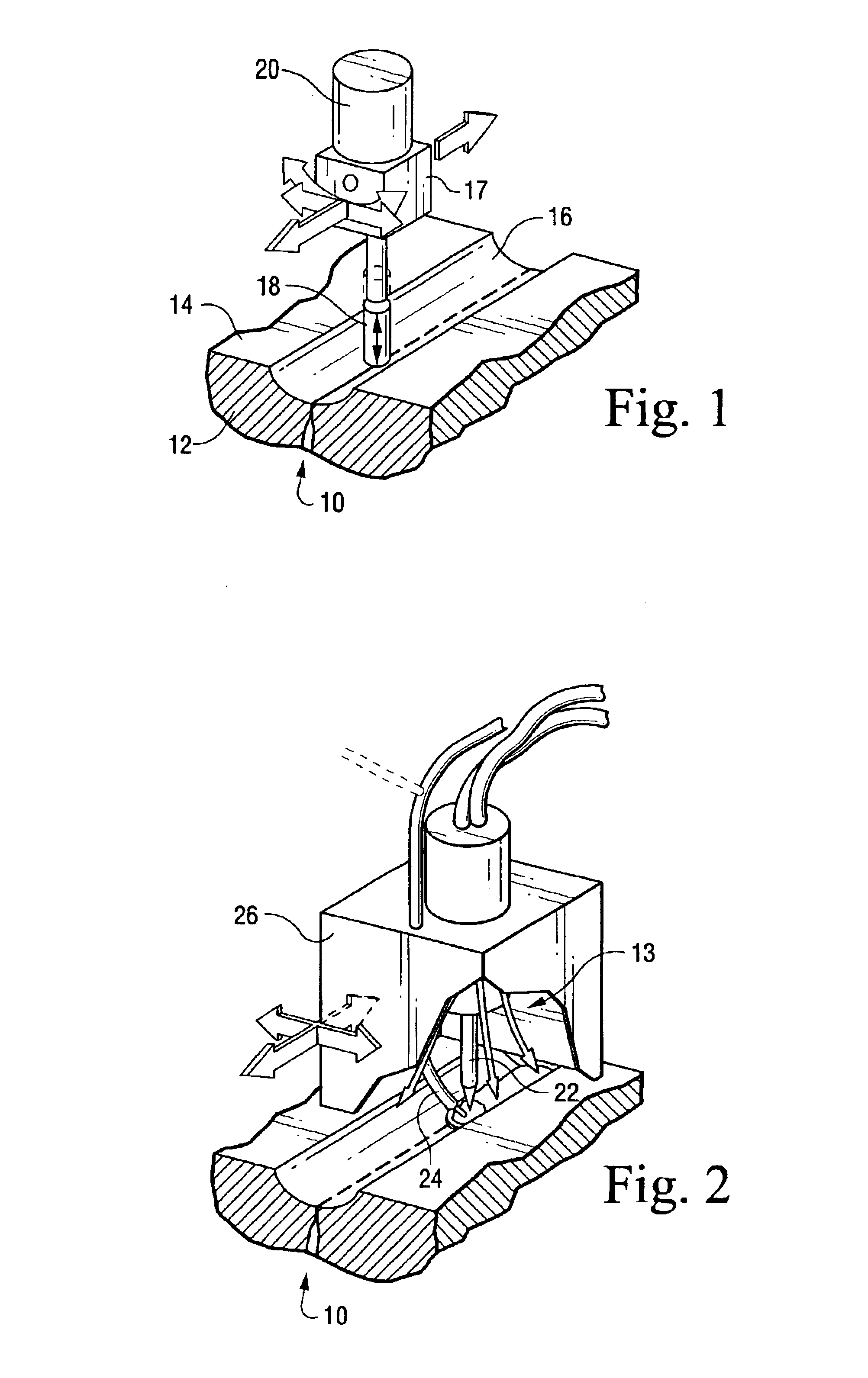
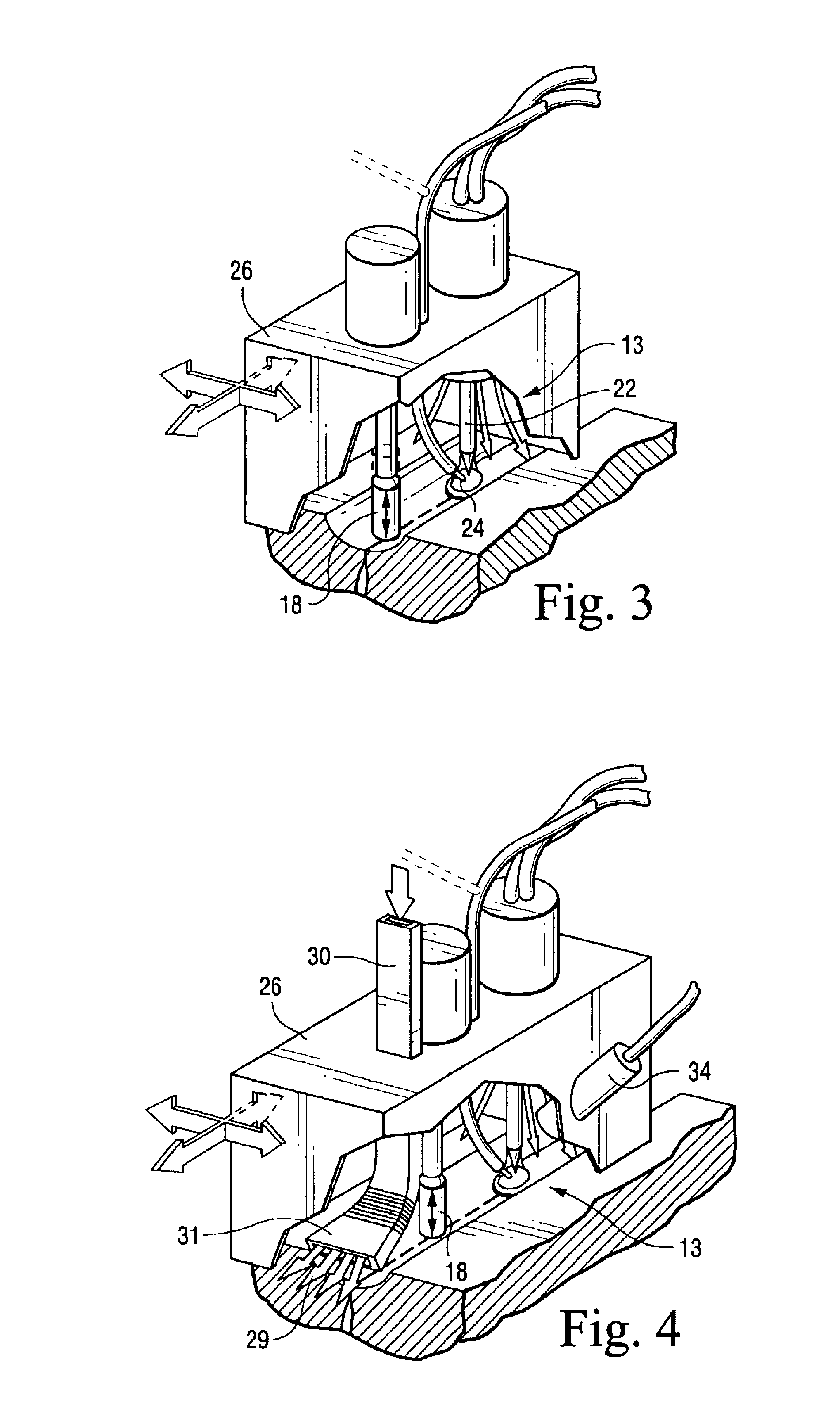
[0023]Referring now to the drawings, particularly to FIG. 1, there is illustrated a tool for plastically deforming one or both margins or sides of a crack to close the crack to form a sealed ligament while retaining an unclosed portion of the crack underlying the sealed ligament. Particularly, the crack, generally designated 10, is formed in a component 12 and is typically exposed through the surface 14 of the component 12. The crack typically extends from the surface 14 and inwardly of the component. In FIG. 1, the surface 14 has been excavated to form a recess or trough 16, although it will be appreciated that the present apparatus and methods may be applied without first excavating the surface 14. Also illustrated in FIG. 1 is a peening tool 17 having a deformation or peening head 18 driven by a transducer 20. The tool is movable linearly in orthogonally-related directions and along a curvilinear path as indicated by the arcuate arrow. The tool head 18 vibrates along its axis, as...


PUM

PropertyMeasurementUnit
Depthaaaaaaaaaa
Heataaaaaaaaaa
Velocityaaaaaaaaaa

Abstract

A component which has a surface crevice or crack and contaminants on at least one face of the opening is welded. The weld is effected by first plastically deforming the surface of the component to close the surface opening to a predetermined depth less than the depth of the opening and contaminated faces defining the opening to form a sealed ligament. The sealed ligament leaves unclosed a portion of the crack below the sealed ligament. The closed surface is hermetically sealed by fusion-welding to a depth of penetration equal to or less than the predetermined depth of the sealed ligament to minimize or eliminate expulsion of contaminants in the sealed ligament.

Description

BACKGROUND OF THE INVENTION[0001]The present invention relates to apparatus and methods for fusion-welding of creviced or defective, e.g., cracked, components having contaminants, e.g., liquid, oxides and the like, trapped in the components and particularly relates to underwater fusion-welding of creviced or cracked components to preclude expulsion conditions leading to porosity and / or blowholes through the weld material.[0002]Intergranular stress corrosion cracks, fatigue cracks, unfused weld material, base metal laminations, joint crevices and other defects which are open to the surface of components submerged in a liquid, e.g., water, trap the liquid within their volume. For example, if the defect has been exposed to a high-temperature liquid, e.g., water environment during service, such as in a nuclear reactor, there is necessarily also an oxide on the creviced or defective surfaces. With the oxide being present, heat from fusion-welding processes typically reduces the oxide to ...

Claims


Application Information

Patent Timeline
IPC IPC(8): B23K9/00
CPCB23K9/0061Y10T29/49618Y10T29/49718
Inventor OFFER, HENRY P.BOURBOUR, SIAMAK
Owner GENERAL ELECTRIC CO
Why Eureka
Try Eureka