Combination self-expandable, balloon-expandable endoluminal device

a self-expanding, endoluminal technology, applied in the field of endoluminal devices, can solve the problems of limited x-ray visibility, self-expanding devices, and the general inability to be manipulated to a larger diameter after deploymen

Inactive Publication Date: 2005-05-10
BOSTON SCI SCIMED INC
View PDF29 Cites 121 Cited by
  • Summary
  • Abstract
  • Description
  • Claims
  • Application Information

AI Technical Summary

Problems solved by technology

That is, balloon expandable devices are not also self-expanding, and self-expanding devices are not typically balloon expandable.
On the other hand, self-expanding devices typically must be sized accurately to provide acceptable outward force and cannot generally be manipulated to a larger diameter after deployment.
Self-expanding devices are typically made of a superelastic material, such as a superelastic grade of nitinol, which has a limited x-ray visibility.
Balloon-expandable devices are typically capable of expansion into a range of sizes, and typically are relatively stiff and inflexible.
Balloon-expandable devices do not typically recover if crushed in the body, however, and are rigid bodies that do not expand and contract with motion of the vessel.
Balloon-expandable devices are also typically longitudinally rigid, limiting delivery through tortuous anatomy.

Method used


Image

  • Combination self-expandable, balloon-expandable endoluminal device
  • Combination self-expandable, balloon-expandable endoluminal device
  • Combination self-expandable, balloon-expandable endoluminal device

Examples


Embodiment Construction

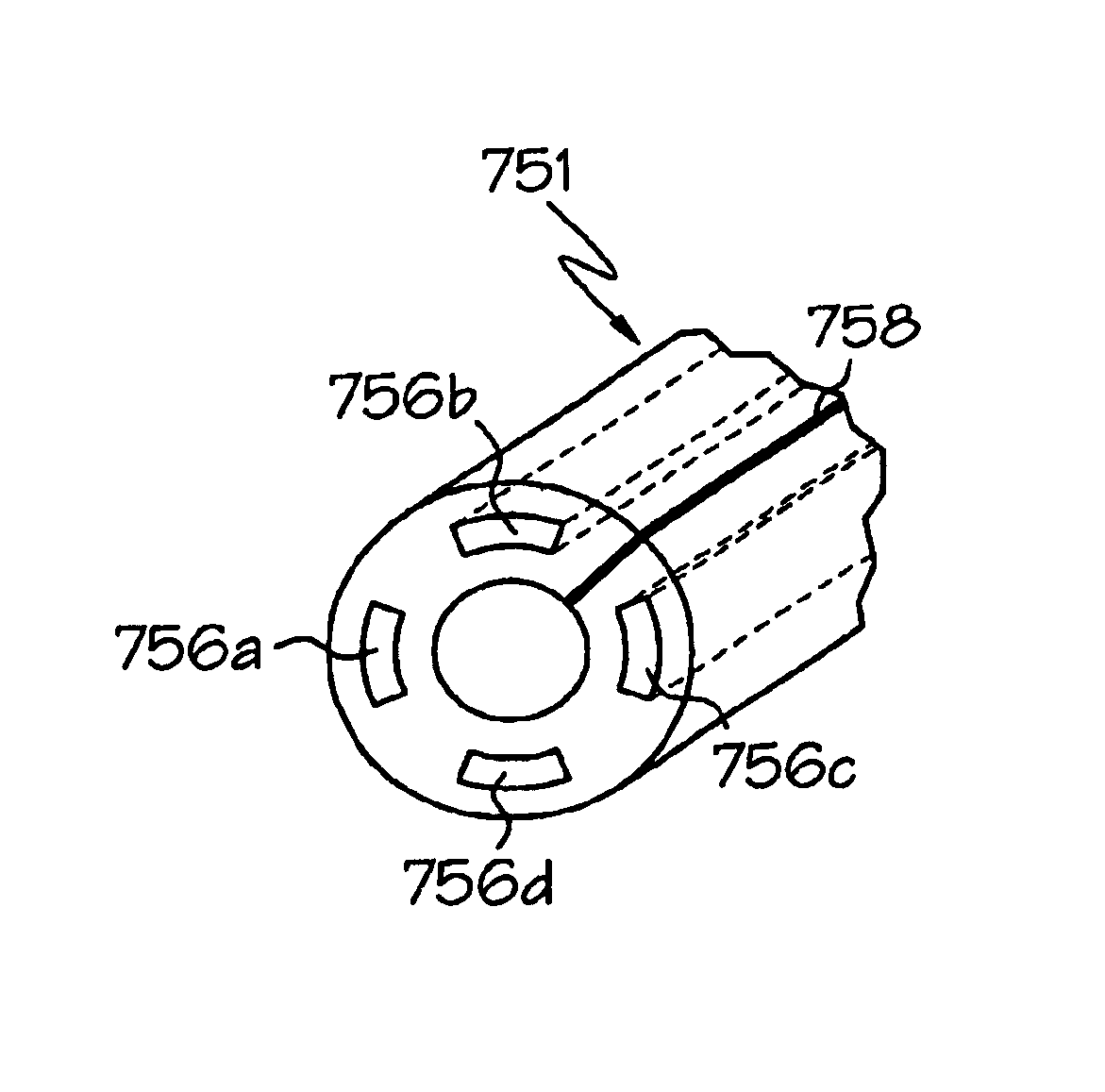
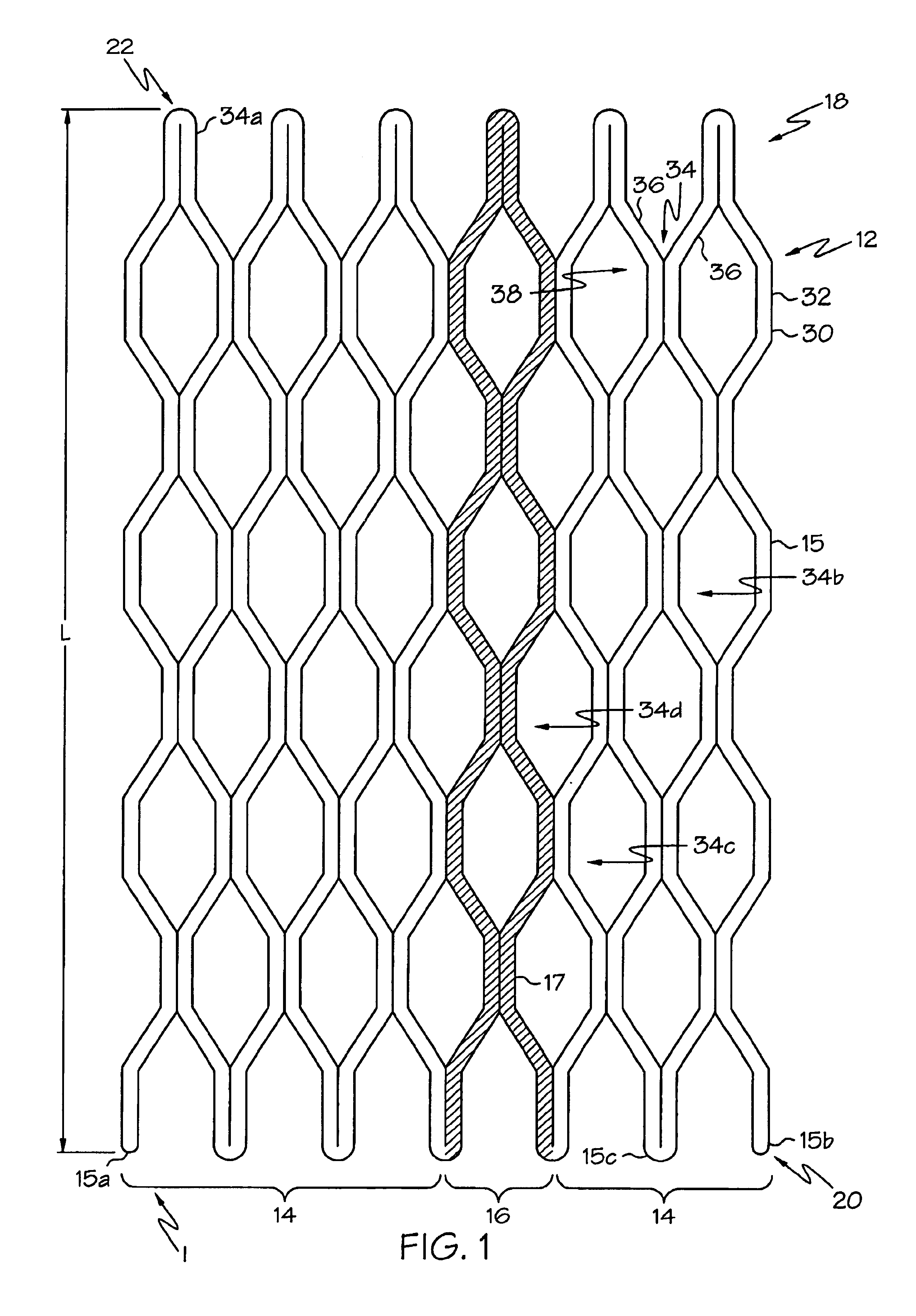
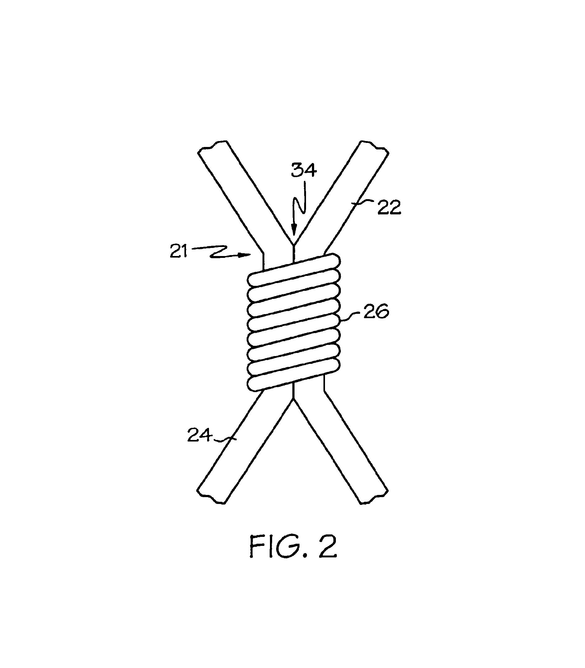
[0044]The invention will next be illustrated with reference to the figures wherein similar numbers indicate the same elements in all figures. Such figures are intended to be illustrative rather than limiting and are included herewith to facilitate the explanation of the apparatus of the present invention.

[0045]Although the term “vena cava filter” technically refers to implantable filters placed in the vena cava—the jugular or femoral veins, which are the typical locations for such filters—the term as used herein refers to any type of implantable filter, regardless of the specific body lumen into which it is implanted. In particular, the anchoring assemblies or portions of vena cava filters shown in U.S. Pat Nos. 5,709,704 and 5,836,939 may be particularly well-suited for construction in accordance with this invention. Vena cava filters are deployed much in the same way as stents, and thus throughout this application the term “endoluminal device” is used to refer to both vena cava fi...


PUM

PropertyMeasurementUnit
thicknessaaaaaaaaaa
superelasticaaaaaaaaaa
diameteraaaaaaaaaa

Abstract

An endoluminal device, such as a stent or a vena cava filter, comprising at least one superelastic section and at least one plastically deformable section. The superelastic section may comprise, for example, a superelastic grade of nitinol, whereas the plastically deformable section may comprise, for example, gold, platinum, tantalum, titanium, stainless steel, tungsten, a nickel alloy, a cobalt ally, a titanium alloy, or a combination thereof. Each plastically deformable section may merely comprise a constrained portion of the superelastic section comprising a plastically deformable material, such as gold. The device enables deployment by a method comprising introducing the device into a body lumen with the device radially constrained in a first configuration having a first diameter; allowing the device to self-expand into a second configuration having a second diameter less than or equal to a fully-self-expanded diameter; and then optionally “fine-tuning” the device by forcibly expanding the device into a third configuration having a third diameter in a range between the second diameter and less than or equal to a fully-forcibly-expanded diameter. The superelastic and plastically deformable sections may be tubular sections placed end-to-end, such that the plastically deformable section can be conformed to fit a tapered section of a lumen.

Description

CROSS-REFERENCE TO RELATED APPLICATIONS[0001]This application is a continuation-in-part of U.S. patent application Ser. No. 09 / 362,261, filed July 28, 1999, now U.S. Pat. No. 6,485,507 the contents of which is incorporated herein in its entirety by reference.TECHNICAL FIELD[0002]This invention relates generally to endoluminal devices such as vena cava filters, stents, grafts, and / or prostheses and, more specifically, to endoluminal devices that have combined self-expanding and balloon-expandable properties.BACKGROUND OF THE INVENTION[0003]A stent is an elongated device used to support an intraluminal wall. In the case of a stenosis, a stent provides an unobstructed conduit for blood in the area of the stenosis. Such a stent may also have a prosthetic graft layer of fabric or covering lining the inside or outside thereof, such a covered stent being commonly referred to in the art as an intraluminal prosthesis, an endoluminal or endovascular graft (EVG), or a stent-graft.[0004]A prost...

Claims


Application Information

Patent Timeline
Patent Type & Authority Patents(United States)
IPC IPC(8): A61F2/06A61F2/00A61B17/00A61F2/01A61F2/90A61L31/00A61M25/01
CPCA61F2/01A61F2/90A61F2/91A61F2/915A61F2002/91541A61F2002/91558A61F2230/0054A61F2250/0018A61F2250/0048A61F2002/018A61F2230/0006A61F2230/0013A61F2210/0019A61L31/18
Inventor WALAK, STEVEN E.
Owner BOSTON SCI SCIMED INC
Why Eureka
Try Eureka