Hydrogen absorbing tank apparatus

a technology of hydrogen absorbing tank and tank body, which is applied in the direction of fluid pressure control, process and machine control, instruments, etc., can solve the problems of low hydrogen gas supply to the fuel cell, low hydrogen producing pressure, insufficient power generation, etc., and achieves the effect of improving start-up performance, increasing utilization rate, and reducing siz

Inactive Publication Date: 2005-05-10
TOYOTA JIDOSHA KK +1
View PDF6 Cites 12 Cited by
  • Summary
  • Abstract
  • Description
  • Claims
  • Application Information

AI Technical Summary

Benefits of technology

[0018]The hydrogen gas consumer device may be a fuel cell from which heat is supplied to the hydrogen absorbing tank. Therefore, quick start of the fuel cell can be realized. The amount of heat quickly generated by the fuel cell can be used to heat the hydrogen absorbing tank so as to accelerate the start-up of the hydrogen absorbing tank. Furthermore, power generated by the fuel cell can be used to operate the gas compressor, so that a battery for storing power for temporary operation of the gas compressor can be reduced in size.
[0019]Heat generated by the gas compressor or the motor that operates the gas compressor may be supplied to the fuel cell or to the hydrogen absorbing tank by using a heating medium. This construction will further improve start-up performance.
[0020]If the hydrogen gas producing pressure of the hydrogen absorbing tank has decreased due to a decrease in the amount of hydrogen stored in the hydrogen absorbing tank, the gas compressor may be operated for supplemental pressurization of hydrogen gas supplied to the hydrogen gas consumer device. This construction increases the utilization rate (effective hydrogen absorbing capacity) of the hydrogen absorbing tank.
[0021]Furthermore, if the hydrogen gas producing pressure of a hydrogen gas generator device that supplies hydrogen gas to the hydrogen absorbing tank is lower than the hydrogen absorbing pressure of the hydrogen absorbing tank, hydrogen gas supplied from the hydrogen gas generator device to the hydrogen absorbing tank may be pressurized. This construction increases the operation e...

Problems solved by technology

However, if the hydrogen absorbing tank for supplying hydrogen gas to the fuel cell has a low temperature, for example, when the vehicle ambient temperature is low, the hydrogen producing pressure becomes low and the amount of hydrogen gas supplied to the fuel cell is low.
In such a case, there is a danger of insufficient power generation, and also a danger of insufficient heat supply from the fuel cell to the hydrogen absorbing tank, which will result in a further delay of the start of power generation of the fuel cell.
A delay of the start of power generation at the time of hydrogen release from the hydrogen absorbing tank also occurs when hydrogen gas is supplied from the hydrogen absorbing tank to a hydr...

Method used


Image

  • Hydrogen absorbing tank apparatus
  • Hydrogen absorbing tank apparatus
  • Hydrogen absorbing tank apparatus

Examples


first embodiment

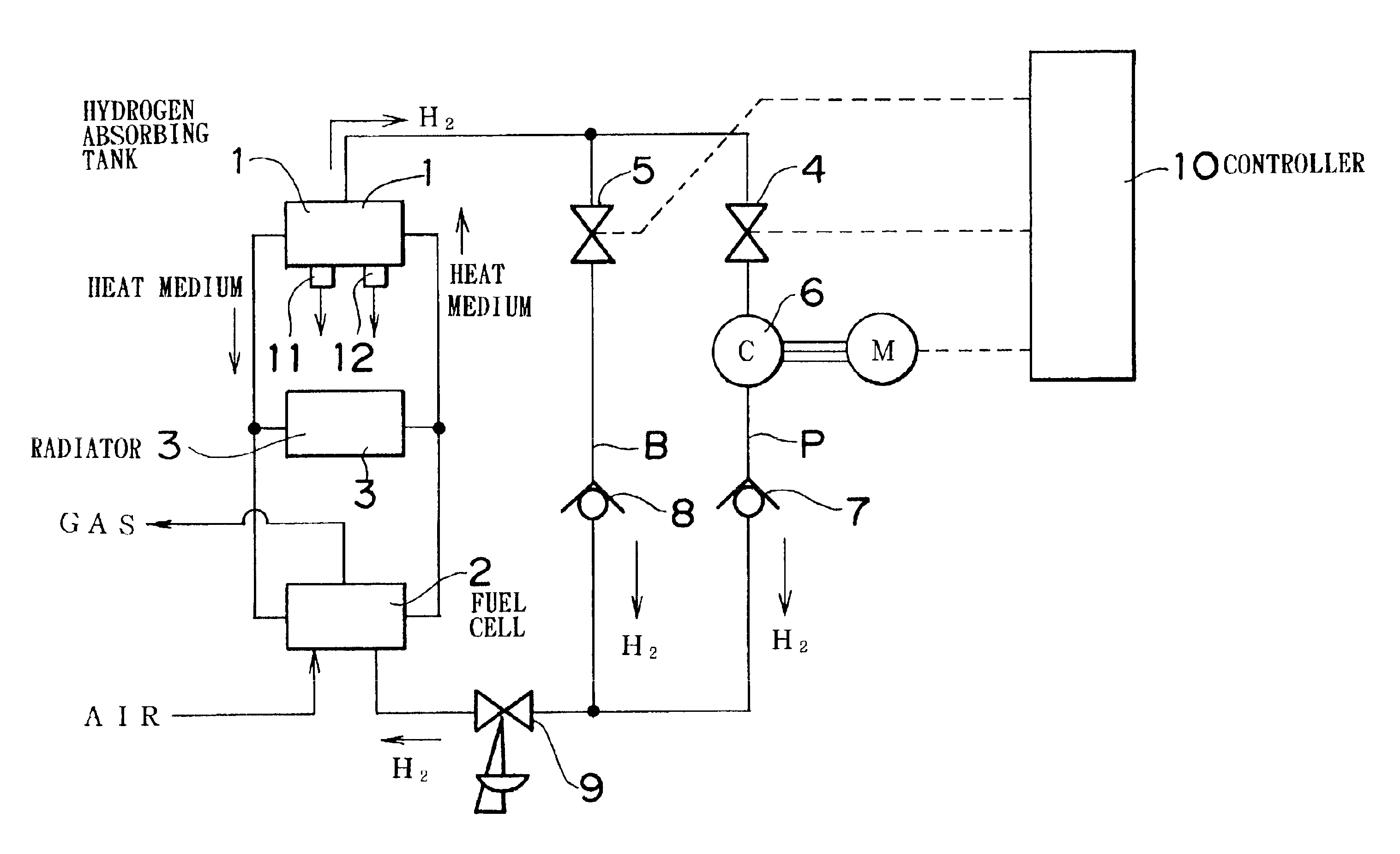
[0030]FIG. 1 is a system diagram of a hydrogen absorbing tank apparatus illustrating a hydrogen gas flow passage in particular.

[0031]Referring to FIG. 1, a hydrogen absorbing tank 1 contains a hydrogen absorbing alloy powder. The hydrogen absorbing tank 1 is connected to a hydrogen-oxygen fuel cell 2 and a radiator 3 by piping. Cooling water, that is, a heating medium, is circulated between the hydrogen absorbing tank 1, the fuel cell 2 and the radiator 3 by using valves and a circulating pump (not shown). During a normal power generating operation, heat generated by the fuel cell 2 is supplied to the hydrogen absorbing tank 1 in order to produce or release hydrogen gas from the hydrogen absorbing tank 1, and a surplus amount of heat is discharged through the radiator 3.

[0032]Hydrogen gas from the hydrogen absorbing tank 1 is supplied to a compression passage P via a control valve 4, and also to a bypass passage B via a control valve 5. The compression passage P is provided with a ...

second embodiment

[0042]A second embodiment will be described with reference to FIG. 3.

[0043]The second embodiment has a construction similar to that of the first embodiment shown in FIG. 1, but is designed so that a heat medium from a hydrogen absorbing tank 1 cools the compressor 6 and the motor M.

[0044]Therefore, the second embodiment is able to prevent the overheating of the compressor 6 and the motor M and to achieve good supplemental heating of the hydrogen absorbing tank 1.

third embodiment

[0045]A third embodiment will be described with reference to FIG. 4.

[0046]The third embodiment is similar to the first embodiment, but differs as follows. That is, a hydrogen gas generator 13 that generates hydrogen gas by reforming methanol is added to the construction shown in FIG. 1. The hydrogen gas generator 13, a hydrogen absorbing tank 1 and a fuel cell 2 are connected to an input pipe of a compressor 6 via control valves 14, 15 and 17, respectively. The hydrogen absorbing tank 1 and the fuel cell 2 are also connected to an output pipe of the compressor 6 via control valves 16 and 18, respectively.

[0047]The operation of this hydrogen gas generator-hydrogen absorbing tank-fuel cell system will be described.

[0048]The flowing of fluid into and out of the hydrogen absorbing tank 1, the fuel cell 2 and the hydrogen gas generator 13 will be described only with reference to hydrogen gas, and will not be described with respect to other fluids.

[0049]When the temperature detected by th...


PUM


Abstract

A gas compressor and a bypass that bypasses the gas compressor are provided between a hydrogen absorbing tank and a hydrogen gas consumer device such as, for example, a fuel cell. When the hydrogen gas generating pressure is low during an initial period of the hydrogen gas releasing operation of the hydrogen absorbing tank, the gas compressor is operated. When the hydrogen gas generating pressure of the hydrogen absorbing tank becomes sufficiently high due to normalization of the operation of the fuel cell or the like, the gas compressor is stopped, and hydrogen gas is supplied to the fuel cell via the bypass.

Description

INCORPORATION BY REFERENCE[0001]The disclosure of Japanese Patent Application No. HEI 10-270995 filed on Sep. 25, 1998, including the specification, drawings and abstract, is incorporated herein by reference in its entirety.BACKGROUND OF THE INVENTION[0002]1. Field of Invention[0003]The present invention relates to hydrogen absorbing tank apparatus.[0004]2. Description of Related Art[0005]In a conventional art, when hydrogen gas that is stored by absorption or occlusion in a hydrogen absorbing tank is to be extracted from the tank and supplied to a fuel cell, the hydrogen absorbing tank needs to be heated by using hot water or the like in order to provide release heat for releasing hydrogen gas from a hydrogen absorbing material. For example, in a system where hydrogen gas is extracted from a hydrogen absorbing tank and supplied to a fuel cell, heat produced by the fuel cell is used to heat a hydrogen absorbing material disposed in the hydrogen absorbing tank.[0006]Furthermore, in o...

Claims


Application Information

Patent Timeline
IPC IPC(8): F02B43/00F02B43/10F17C11/00H01M8/06H01M8/04
CPCF02B43/10F17C11/005H01M8/065H01M2250/20Y02T90/42Y02T90/32Y02T10/32Y02E60/50Y02E60/321Y02E60/32Y02T10/30Y02T90/40
Inventor FUJITA, NOBUOKUBO, HIDEHITO
Owner TOYOTA JIDOSHA KK
Why Eureka
Try Eureka