Device for treating powder particles by rotary flow

a technology of fluidized bed and powder particles, which is applied in the direction of lighting and heating apparatus, drying machines, furnaces, etc., can solve the problems of inability to carry out control to form a satisfactory fluidized bed, and inability to uniformly fluidize and disperse powder particles, etc., to achieve optimal operation control, efficient discharge of gas, and the effect of improving the product collection ra

Inactive Publication Date: 2005-05-17
NARA MACHINERY
View PDF6 Cites 18 Cited by
  • Summary
  • Abstract
  • Description
  • Claims
  • Application Information

AI Technical Summary

Benefits of technology

[0009]Another object of the present invention is to solve the problems facing actual making of products described above, and to cause slowing of discharge velocity of gas that has been introduced inside the treatment chamber at an axial region inside the treatment chamber where discharge velocity is high with weak centrifugal force. By doing this, it is possible to efficiently discharge gas that has been introduced into the treatment chamber while balancing centripetal force and centrifugal force on the powder particles regardless of the particle size, and it is possible to carry out optimal operation control of introduction and discharge of gas for fluidized bed behavior. It is also possible to anticipate improved product collection rate by reducing the amount of powder particles sticking to a bag filter accompanying gas flow, and re

Problems solved by technology

However, since cohesiveness and adhesiveness increase rapidly as particle diameter of the processing material becomes smaller, it is not possible to uniformly fluidize and disperse the powder particles with the previously described existing fluidized bed apparatus.
On the other hand, there is a problem that if the amount of heated air supplied is increased in order to achieve uniform fluidization and dispersion, the body of fine powder particles will fly out as it is, handling is extremely difficult, and it is not possible to carry out control to form a satisfactory fluidized bed.
Therefore, with the fluidized bed apparatus of the related art, there is a

Method used


Image

  • Device for treating powder particles by rotary flow
  • Device for treating powder particles by rotary flow
  • Device for treating powder particles by rotary flow

Examples


first embodiment

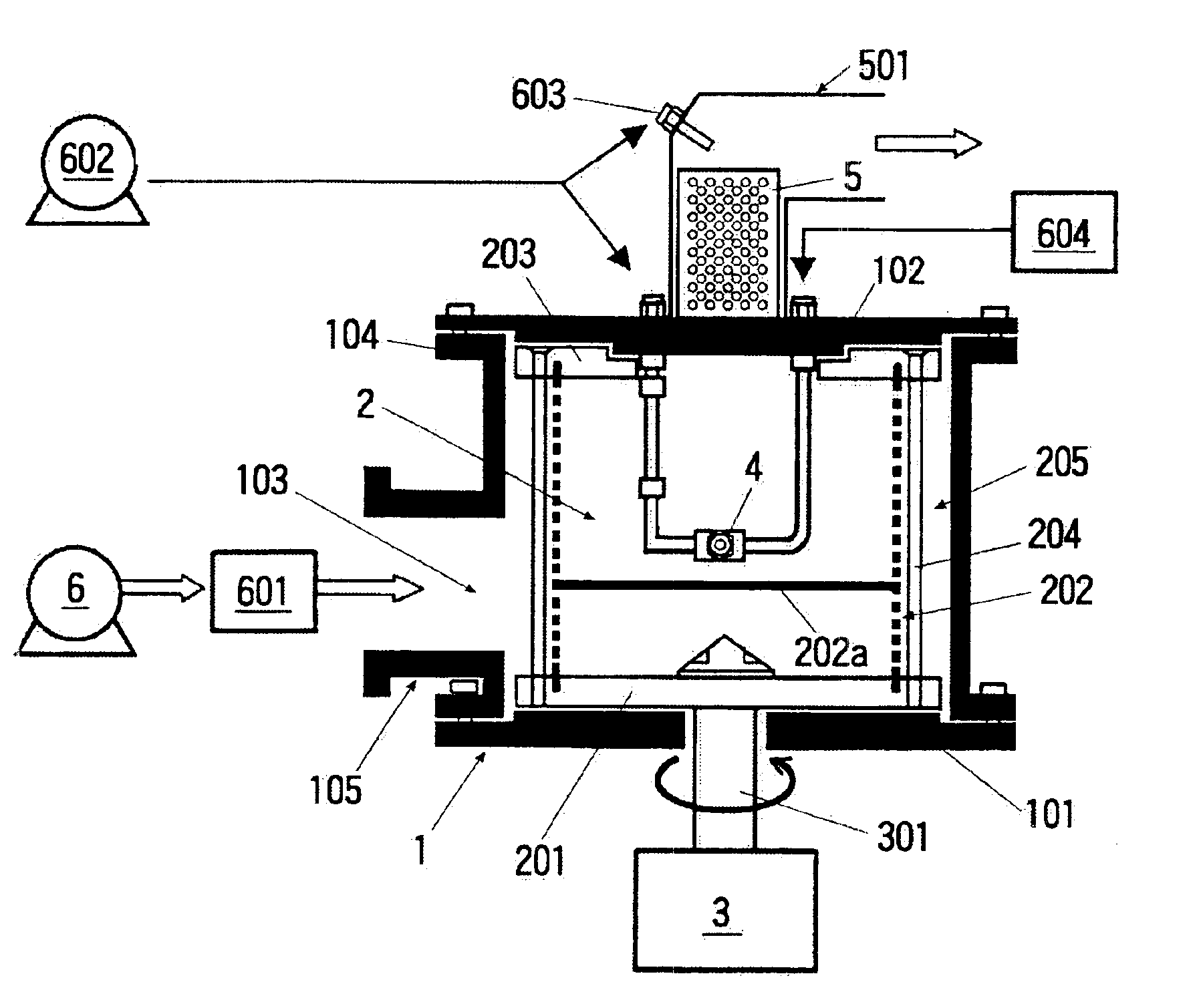
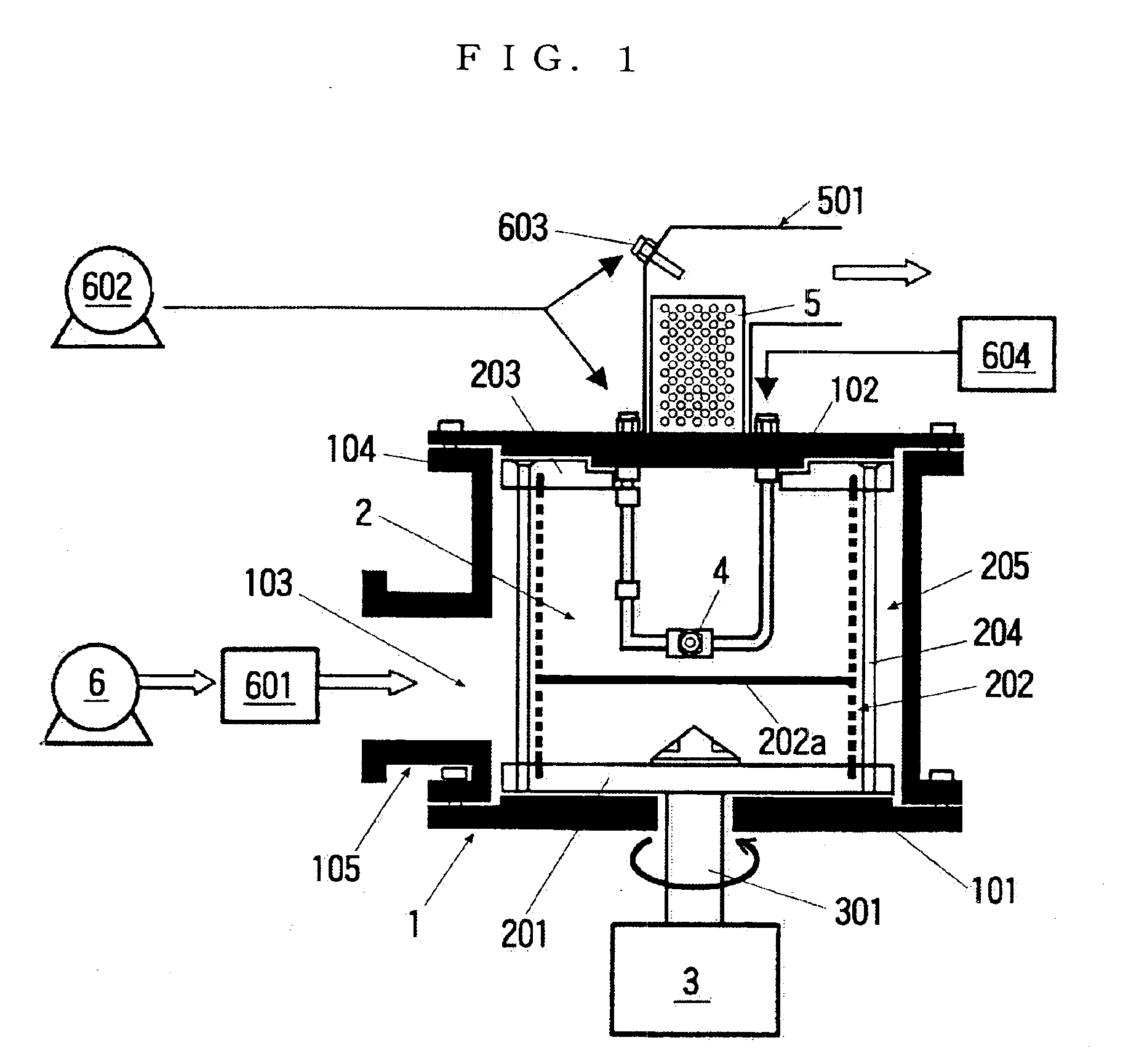
[0051]Also, the supply port 113 for introducing a specified gas (various gasses such as heated air, inert gas etc.) into the air circulation path 215 is formed in a right upper part of the casing 1, and is adapted to cause gas that has been introduced from the supply port 113 to circulate along the inner surface of the casing 1, as shown in FIG. 11. For example, in the case of introducing heated air, air generated by a blower 6, as with the gas inflow means of the first embodiment shown in FIG. 1, is heated by the heater 601 and introduced to the supply port 113.

[0052]The treatment chamber 2 is formed so that a disk-shaped rear fixed plate 211 and a disk-shaped cover body 216 formed of transparent acrylic resin are opposite each other with a specified distance between them, with a circular dispersion plate 212 fitted between them. The fixed plate 211 and the cover body 216 are connected by a plurality of bolts 214, and attachment and detachment of the cover body 216 and the dispersi...

second embodiment

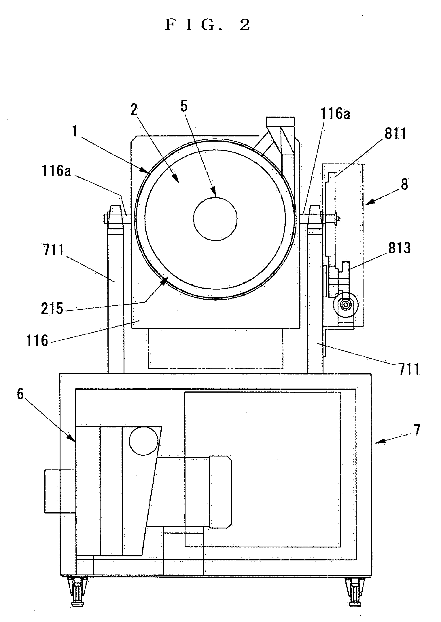
[0057]FIG. 10 is a schematic cross sectional drawing showing another example for driving the bag filter 5 of the In the processing apparatus shown in FIG. 10, the rotation operation lever 515 is not provided on the discharge pipe 511, and the structure is such that powder particles on the bag filter 5 are made to fall by causing the bag filter 5 to rotate using drive force of the motor 3. A pulley 315 is provided on the discharge pipe 511 of this embodiment instead of the rotation operation lever 515. Pulleys 312 and 316 are provided next to each other on a motor shaft 311, and a so-called dual rotation axis mechanism is adopted to convey drive force of the motor 3 to the discharge pipe 511 via a transmission belt 317 suspended between the pulleys 315 and 316. With rotation of the dispersion plate 212 and the bag filter 5 by drive force of the motor 3, a transmission ratio is set such that angular velocity of the bag filter 5 and angular velocity of the dispersion plate 212 do not ...

third embodiment

[0106]In the present invention having this type of structure, a fluidized bed of powder particles is formed by gas flowing into a cylindrical treatment chamber 2 from a circumferential surface region, and mixing, granulation and drying treatment is carried out. At this time, at a dispersion plate (circumferential plate) 212 side, as ventilation means, being the outermost section of the treatment chamber 2, and at a bag filter 5 side at a central section, the flow rate is faster at the central side, as result of which it becomes easier for finer particles accompanying the gas flow to move to the central section and a phenomenon arises where it is difficult for the moved particles to return to the circumferential surface region. Also, when blockage of the bag filter 5 occurs discharge efficiency becomes bad and there is a danger of pressure drop and the balance between centrifugal force and centripetal force collapsing.

[0107]However, the bag filter 5 provided in the treatment chamber ...


PUM

PropertyMeasurementUnit
Speedaaaaaaaaaa
Widthaaaaaaaaaa
Permeabilityaaaaaaaaaa

Abstract

The present invention relates to a rotating fluidized bed apparatus for powder particle. A gas circulation path is formed at the periphery of the treatment chamber 2 via the circumferential faceplate 202, 212, and the circumferential faceplate is adapted to rotate around an axis. Behavior of powder particles can be controlled by introducing gas from the periphery of the treatment chamber via the circumferential plate 212 to exert centripetal force on the powder particle, while exerting centrifugal force on the powder particles accompanying rotation of the circumferential plate 212. In another aspect, by making the arrangement proportion of the bag filter 5 inside the treatment chamber 2 wider than the surface width of the dispersion plate 212 or larger than the surface area of the dispersion plate 212, it is possible to cause gas that has flowed into the treatment chamber 2 to be discharged at a lower rate at an axial region inside the treatment chamber 2 where centrifugal force is weak and discharge rate is fast. It is possible to carry out optimal operation control of introduction and discharge of gas for fluidized bed behavior.

Description

TECHNICAL FIELD[0001]The present invention is in the field of fluidized bed apparatus for treating powder particles by mixing, granulating, coating, surface treatment, drying, reaction etc., and particularly relates to a fluidized bed apparatus suitable for treating fine powder particles.BACKGROUND ART[0002]Generally, a fluidized-bed apparatus, as shown in FIG. 20, is known as a device for allowing mixing, granulation, coating, drying or reaction of powder particles by causing a gaseous body such as various gases or air to flow in to the inside of a treatment chamber.[0003]This fluidized-bed apparatus is formed of a truncated cone-shaped container 2A having a dispersion plate 3A (for example, a punched porous plate) for ventilation arranged at the bottom. When this apparatus is used to dry powder particles, heated air is made to flow in to the container 2A from below the dispersion plate 3A, and powder particles 1A put inside the container 2A are dried while being subjected to suspe...

Claims


Application Information

Patent Timeline
IPC IPC(8): B01J2/16B01J8/38B01J8/24B01F13/00B01F13/02B01F7/32B01F7/16B01F3/12B01F9/00B01F27/96B01F33/40
CPCB01F7/32B01F13/02B01J8/38B01J2/16B01F13/0255B01F9/00B01F2003/1264B01F23/566B01F29/00B01F27/96B01F33/40B01F33/406B01F23/60
Inventor WAKAMATSU, YOSHIHIROWATANO, SATORU
Owner NARA MACHINERY
Why Eureka
Try Eureka