
Rotatable control lever mount

a technology of lever mount and lever, which is applied in the direction of cycle equipment, manufacturing tools, cycle, etc., can solve the problems of b>1/b> of the lever mount of the myers patent, damage to other components mounted on the handlebar, and render the myers lever mount arrangement b>1/b> undesirable, etc., and achieves the effect of little resistan

Inactive Publication Date: 2005-05-17
BARNETT ROBERT L
View PDF21 Cites 12 Cited by
  • Summary
  • Abstract
  • Description
  • Claims
  • Application Information

AI Technical Summary

Benefits of technology

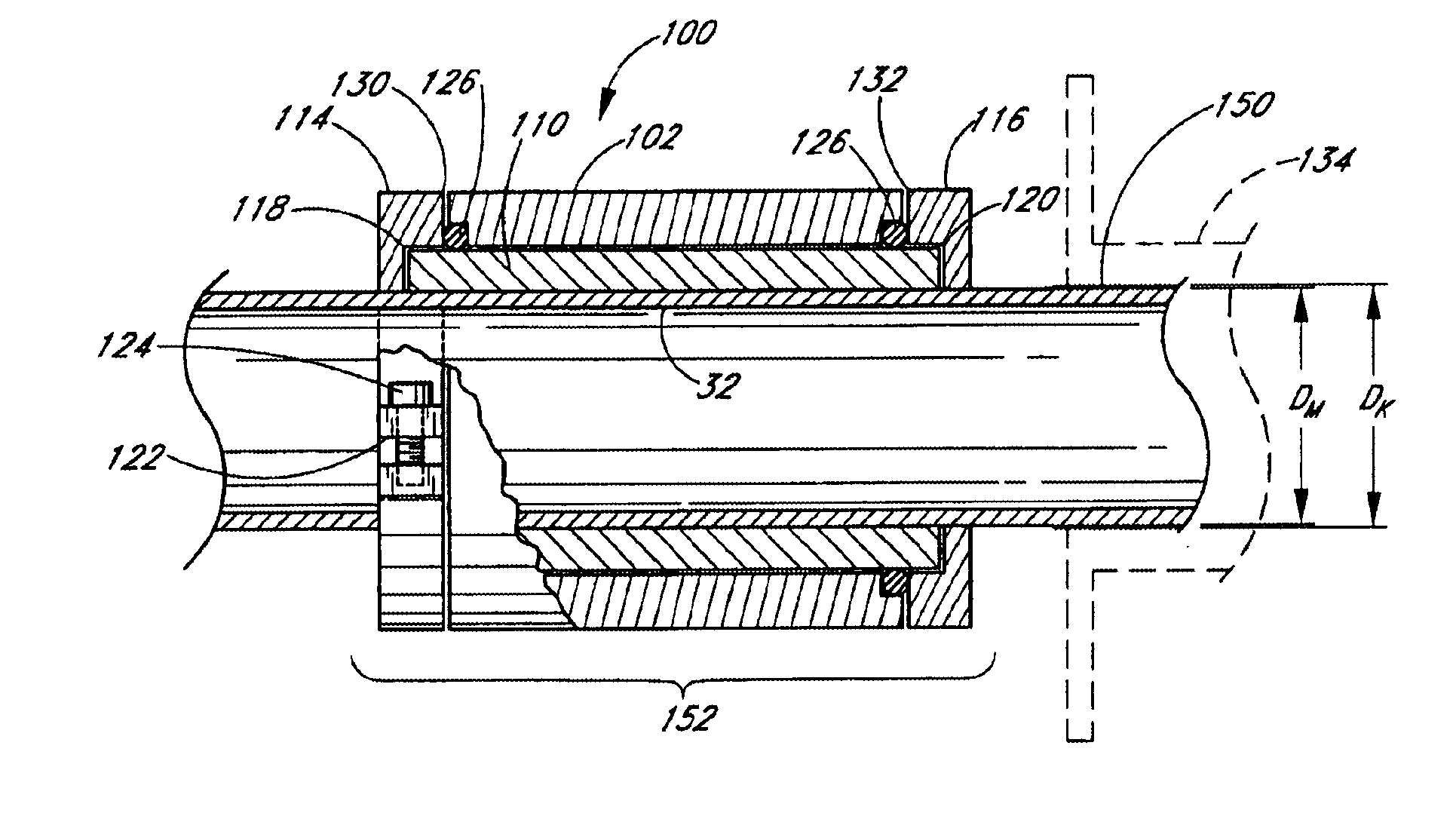
[0012]A preferred embodiment is a control lever mount for mounting a control lever to a handlebar. The handlebar defines a handlebar axis and an outer end portion comprising a control lever mount location and a hand grip portion. The mount includes a sleeve, an internal surface of the sleeve defining a first diameter. The first diameter is sized such that the sleeve may be positioned around the handlebar at the mount location. The sleeve includes a slot configured to permit the first diameter to be reduced such that the sleeve may be secured to the handlebar. At least one clamp portion secures the sleeve to the handlebar. A body portion has a lever support portion configured to pivotally support a control lever for rotation about a pivot axis. The body portion is supported by the sleeve and is rotatable about the handlebar axis. A detent arrangement is configured to releasably secure the body portion in an angular orientation with respect to the handlebar axis and permits the body portion to move from the angular orientation in response to a moment above a predetermined threshold being applied to the body portion. A first stop portion is arranged to contact the body portion to prevent movement of the body portion along the handlebar axis beyond the first stop in a first direction and a second stop portion is arranged to contact the body portion to prevent movement of the body portion along the handlebar axis beyond the second stop in a second direction opposite the first direction.

Problems solved by technology

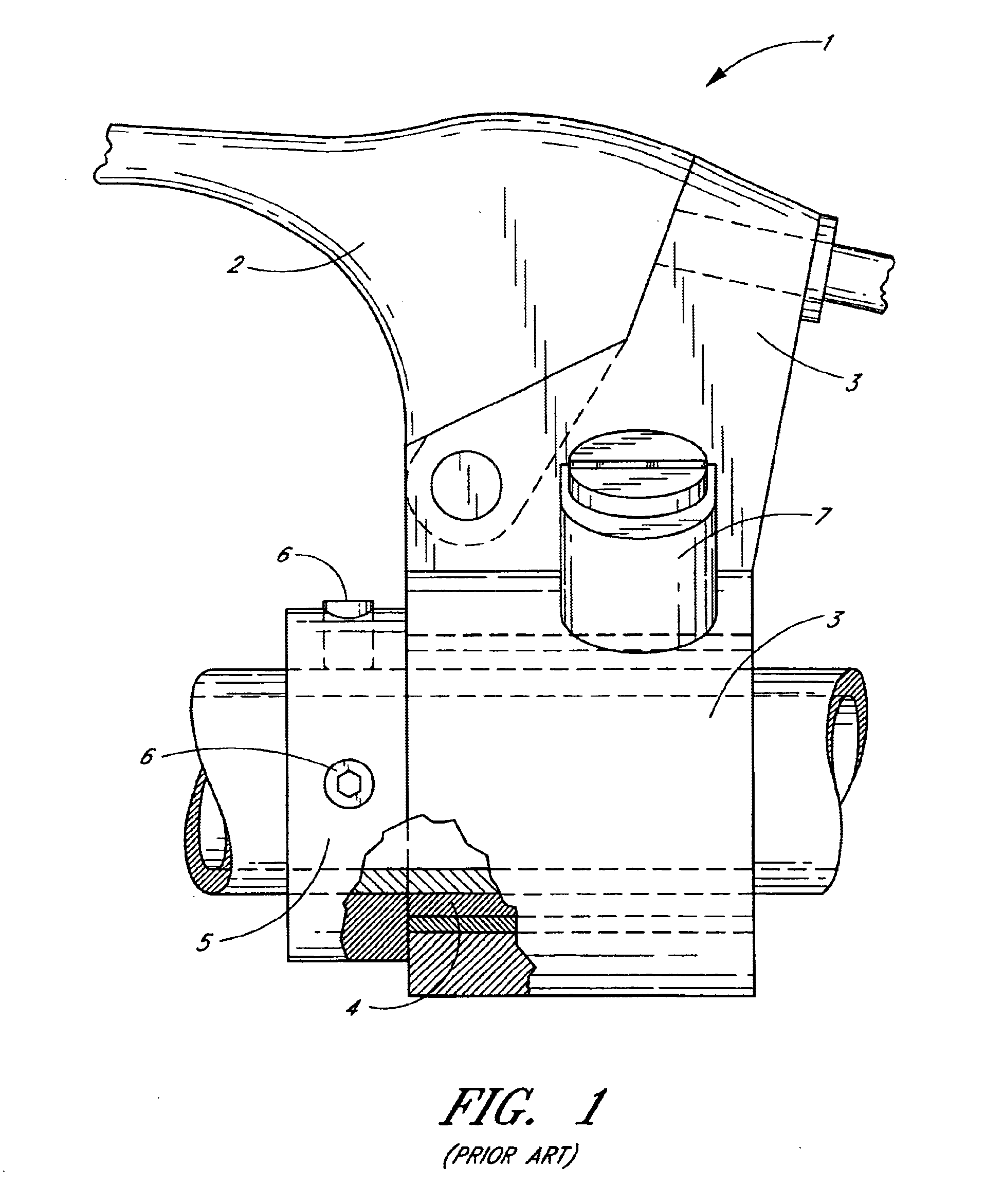
While offering some protection to the lever 2 and the lever mount assembly 1, the lever mount 1 of the Myers patent is undesirable in that it allows axial movement of the perch 3.
When the perch 3 moves axially, it may damage other components mounted on the handlebar, such as an engine stop button, for example.
Particularly in the context of racing events, the time necessary to reposition or “reset” the lever perch 3 onto the sleeve 4 renders the Myers lever mount arrangement 1 undesirable.
Further, the sleeve 4 arrangement of the Myers lever mount 1 is likely to be unstable when mounted on a handlebar.
Furthermore, the pressure applied to the handlebar due to the small area of the set screws 6 may damage relatively thin, aluminum handlebars that are presently preferred in motorcycle racing and may render the Myers lever mount 1 unusable with handlebars constructed from other materials, such as composites, for example.
However, this method also has a number of disadvantages.
For example, because the lever mount must be loosely clamped to the handlebar in order to ensure it can move when necessary, the lever mount may move at times when it is undesirable.
Accordingly, lever damage may occur if this frictional force is too high.
Further, repositioning of the lever is difficult due to such frictional force between the lever mount and the sleeve.

Method used


Image

  • Rotatable control lever mount
  • Rotatable control lever mount
  • Rotatable control lever mount

Examples


Embodiment Construction

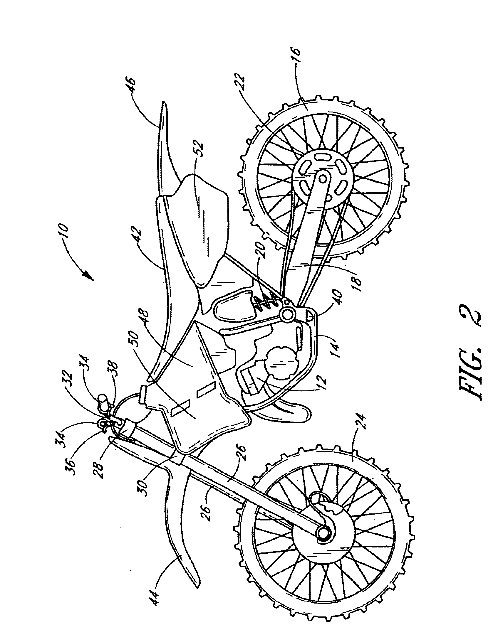
[0024]The present invention finds utility with a number of vehicles, including, without limitation, motorcycles, bicycles, all terrain vehicles (ATVs) and other types of vehicles where control levers may be employed. In addition, advantages present in preferred embodiments may be realized with a number of different control lever functions, such as for use with a manual clutch or braking system, for example. Illustrated embodiments of the control lever mounts, however, are particularly suited for use with a cable-actuated manual clutch lever of an off-road motorcycle.

[0025]With reference to FIG. 2, an off-road motorcycle, generally referred to by the reference numeral 10, is shown. Preferably, an internal combustion engine 12 and associated transmission is mounted within a frame 14 of the motorcycle 10. A rear wheel 16 is connected to the frame through a rear suspension system comprised of a swing arm 18 and a rear shock absorber 20. Preferably, the rear wheel is driven by the engine...


PUM


Abstract

A control lever mount assembly suitable for use in connection with an off-road motorcycle. The lever mount assembly includes a lever-supporting portion, or perch, which is configured to rotatably support a control lever. A sleeve is secured to the handlebar and supports the perch for rotation about an axis of the handlebar. A detent assembly secures the perch in a desired angular orientation relative to the sleeve and the handlebar. The detent assembly is configured to permit rotation of the perch in response to a force being imparted to the lever and / or perch during a crash or fall to protect the perch and lever from damage. Preferably, one or more clamp members are configured to apply a clamping force to the sleeve over a relatively large surface area to prevent damage to the handlebar. A slot may be provided in the sleeve to permit the sleeve to be compressed around the handlebar for a secure fit.

Description

BACKGROUND OF THE INVENTION[0001]1. Field of the Invention[0002]The present invention relates generally to control lever assemblies for operating a control system of a vehicle. More specifically, the present invention relates to a rotatable control lever mount to inhibit breakage of the control lever, especially suited for use with a front brake or a manual clutch system of an off-road motorcycle.[0003]2. Description of the Related Art[0004]Motorcycle control levers are commonly mounted to the motorcycle's handlebar to permit a rider to operate a control system of the motorcycle, such as a manual clutch system or a front brake system. Typically, the control lever is rotatably supported by a lever mount, which is clamped to the handlebar on an inward side of a handgrip. The control lever rotates about a pivot axis to impart a pulling force on a bowden wire arrangement (or impart a pushing force on a hydraulic piston, if the control system is hydraulically actuated) and thereby operat...

Claims


Application Information

Patent Timeline
IPC IPC(8): B62K23/00B62K23/06B62K11/00B62K11/14
CPCB62K11/14B62K23/06Y10T403/4958Y10T74/20438Y10T74/2028
Inventor BARNETT, ROBERT L.
Owner BARNETT ROBERT L
Learn More