
High temperature silicone based subsea insulation

a silicone-based, subsea technology, applied in the direction of insulation, sealing/packing, borehole/well accessories, etc., can solve the problems of inherently brittleness, inability to meet the requirements of insulation, and hydrate formation in equipmen

Inactive Publication Date: 2005-05-17
FMC TECH INC
View PDF17 Cites 11 Cited by
  • Summary
  • Abstract
  • Description
  • Claims
  • Application Information

AI Technical Summary

Benefits of technology

[0010]The thermal insulation material of the present invention exhibits many advantageous properties which make it particularly suitable for use on hydrocarbon production equipment. The matrix material is highly flexible, which makes the insulation material resistant to cracking under thermal and mechanical stresses. In addition, the insulation material produces no by-products or exothermic effects during curing and can therefore be cast-in-place in thick sections. Furthermore, due to its relatively low thermal conductivity, the insulation material is an excellent insulator. Moreover, the insulation material can withstand extreme temperatures in excess of 300° F. without detriment to its thermal or mechanical properties.

Problems solved by technology

If the stagnant fluids approach the seawater temperature, hydrates can form in the equipment and block the flow of the fluid.
In many subsea wells, especially those in deep water, the insulation requirements are further complicated by the extreme temperatures of the hydrocarbon fluids exiting the well.
Although insulation materials exist which can withstand these relatively high temperatures, they are inherently brittle.
Therefore, these materials are unable to meet the flexibility and impact resistance requirements of many applications.
Furthermore, because of their brittle nature and exothermic curing properties, these materials are difficult and expensive to install and repair.
Conversely, existing insulation materials which exhibit acceptable flexibility and impact resistance characteristics are unable to withstand the relatively high flow temperatures present in may deep water wells.

Method used


Image

  • High temperature silicone based subsea insulation

Examples


Embodiment Construction

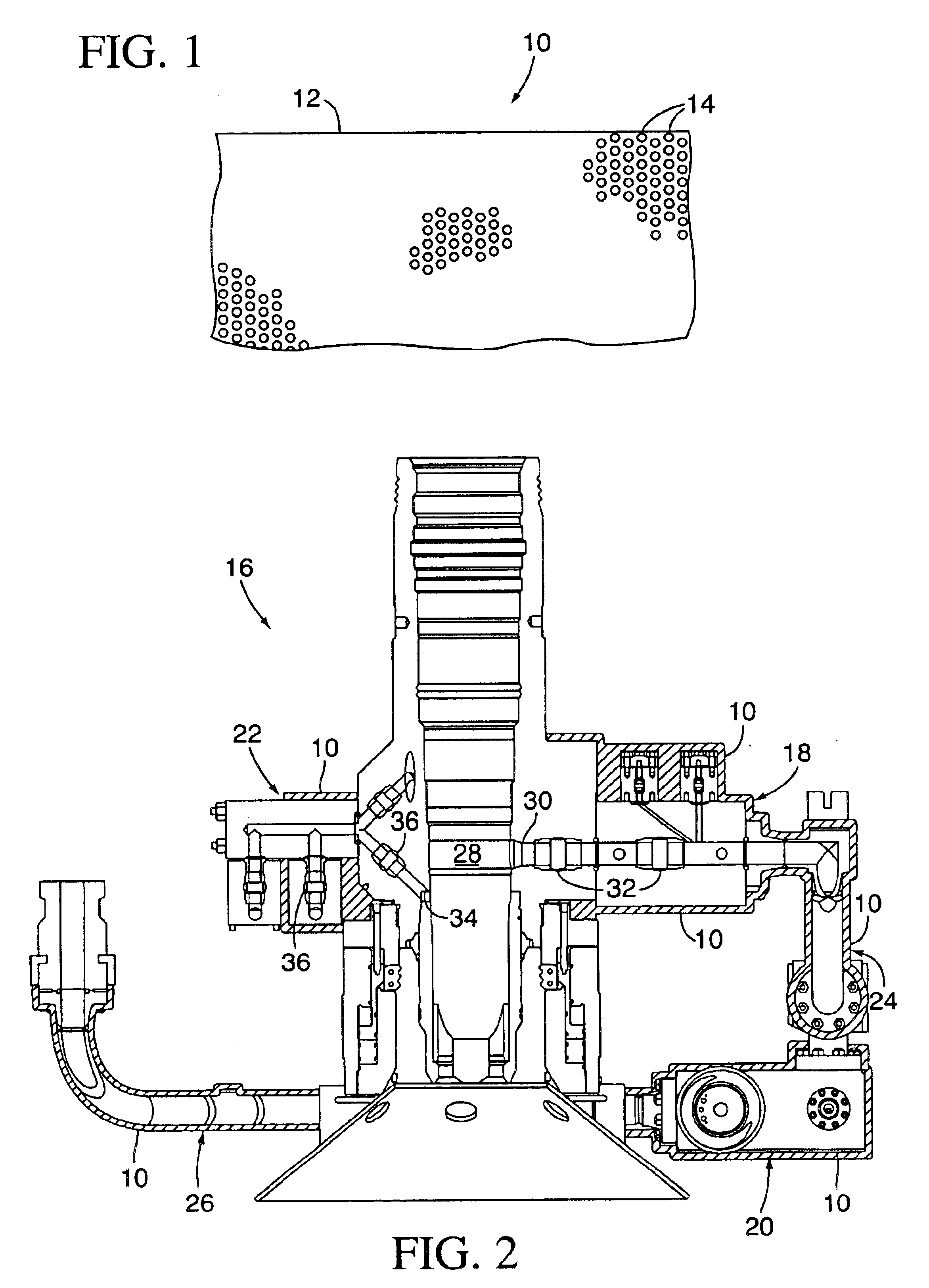
[0014]The present invention is an insulation material which is suitable for subsea oil and gas production equipment. Referring to FIG. 1, the insulation material, which is indicated generally by reference number 10, comprises a matrix 12 and a plurality of micro beads 14 which are supported in the matrix. The matrix 12 ideally comprises a suitable silicone material. More preferably, the matrix 12 comprises an addition cured silicone material. In accordance with one embodiment of the present invention, the matrix 12 comprises a platinum cured, addition cured silicone material, such as the Silastic® E RTV silicone rubber product which is available from Dow Corning Corporation.

[0015]In the context of the present invention, addition cured silicones are preferred over condensation cured silicones because they produce no byproducts or exothermic effects during curing and are therefore more suitable for casting in thick sections. In contrast, condensation cured silicones require moisture f...


PUM

PropertyMeasurementUnit
Pressureaaaaaaaaaa
Diameteraaaaaaaaaa
Percent by volumeaaaaaaaaaa

Abstract

The invention is an insulation material which comprises a silicon based matrix and a plurality of non-metallic beads supported in the matrix. In one embodiment of the invention, the matrix comprises a platinum cured, addition cured silicon material and the beads comprise a mean diameter of less than about 60 microns and an isostatic strength of at least about 10,000 psi. The insulation material may be used in conjunction with subsea oil and gas production equipment, such as pipelines, wellheads and christmas trees.

Description

[0001]This application is a continuation of U.S. patent application Ser. No. 10 / 185,881 filed on Jun. 27, 2002 now U.S. Pat. No. 6,746,761 which is based on U.S. Provisional Patent Application No. 60 / 302,926 filed on Jul. 3, 2001.BACKGROUND OF THE INVENTION[0002]The present invention relates to an insulation material for use on subsea oil and gas production equipment.[0003]When subsea oil and gas wells are located at depths of 5,000 feet or more, the pipelines and wellhead equipment are exposed to seawater which is just a few degrees above freezing. This same temperature can exist in shallow water at extreme latitudes, such as in the North Sea. During a temporary well shutdown, hot produced hydrocarbon fluids within the production equipment become stagnant and are cooled by the surrounding seawater. If the stagnant fluids approach the seawater temperature, hydrates can form in the equipment and block the flow of the fluid.[0004]Thermal insulation is sometimes installed around hydroc...

Claims


Application Information

Patent Timeline
IPC IPC(8): C08K7/00C08K7/28E21B36/00
CPCC08K7/28E21B36/00C08L83/04Y10T428/254Y10T428/31663
Inventor JANOFF, DWIGHT D.
Owner FMC TECH INC
Learn More