Acoustic attenuator

a technology of attenuator and attenuator body, which is applied in the field of attenuator, can solve the problems of difficult difficult to achieve normal conversation and comfortable television listening, and leave very little space for effective noise treatment, etc., to achieve the effect of reducing broad band noise, broad band noise reduction, and increasing noise absorption

Inactive Publication Date: 2005-05-17
ACOUSTIC HORIZONS
View PDF14 Cites 32 Cited by
  • Summary
  • Abstract
  • Description
  • Claims
  • Application Information

AI Technical Summary

Benefits of technology

[0009]An acoustical reflective and dissipative attenuation system is disclosed that is used to reduce broad band noise in the intake air duct (also referred to as a return air duct) of an HVAC heat exchange system. In many cases, the intake air duct is a very short section of the air duct system with very limited workspace, generally less than 20 cubic feet in volume. Significant broad band noise re

Problems solved by technology

Therefore, noise generated by HVAC system, when travelling upstream through the very short intake air duct, exits the intake air filter and enters the building living area creating a noise pollution problem.
This noise pollution makes normal conversation and comfortable television listening difficult.
However, these attempts generally address the treatment at the exhaust air duct section, and not the treatment at the intake air duct section.
Because the intake air duct section is usually a very short section of the air duct, it leaves very little space for any effective noise treatment.
However, these liners are often not desirable because of large space requirements and the extended length of coverage that is required to produce adequate attenuation.
Broad band attenuation is more difficult to achieve with reactive silencers, due to the larger area required to achieve a noticeable result.
To achieve broad band frequency attenuation with an acoustic resonator require

Method used


Image

  • Acoustic attenuator
  • Acoustic attenuator
  • Acoustic attenuator

Examples


Embodiment Construction

[0036]A detailed description of a preferred embodiment of the invention is provided below. While the invention is described in conjunction with that preferred embodiment, it should be understood that the invention is not limited to any one embodiment. On the contrary, the scope of the invention is limited only by the appended claims and the invention encompasses numerous alternatives, modifications and equivalents. For the purpose of example, numerous specific details are set forth in the following description in order to provide a thorough understanding of the present invention. The present invention may be practiced according to the claims without some or all of these specific details. For the purpose of clarity, technical material that is known in the technical fields related to the invention has not been described in detail so that the present invention is not unnecessarily obscured.

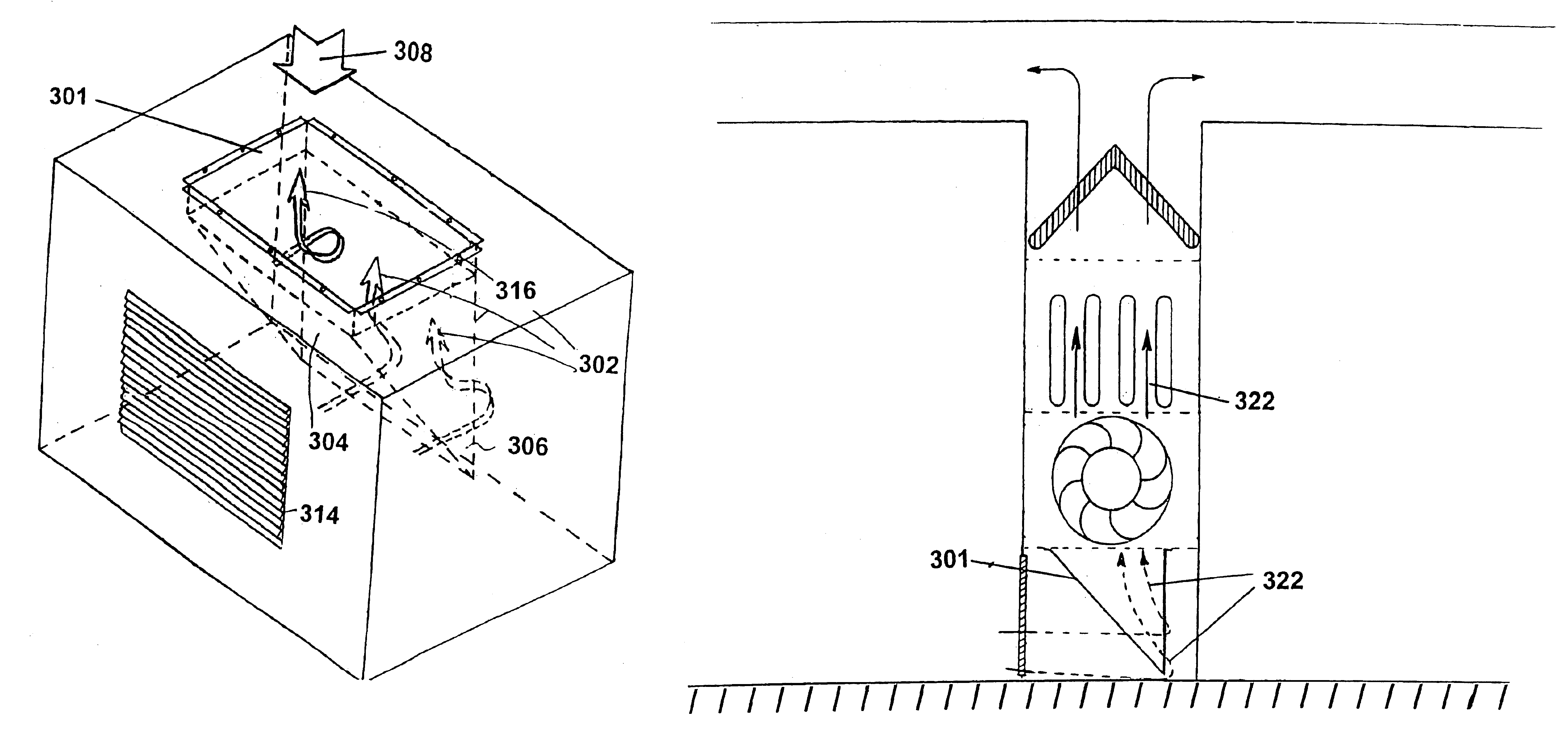
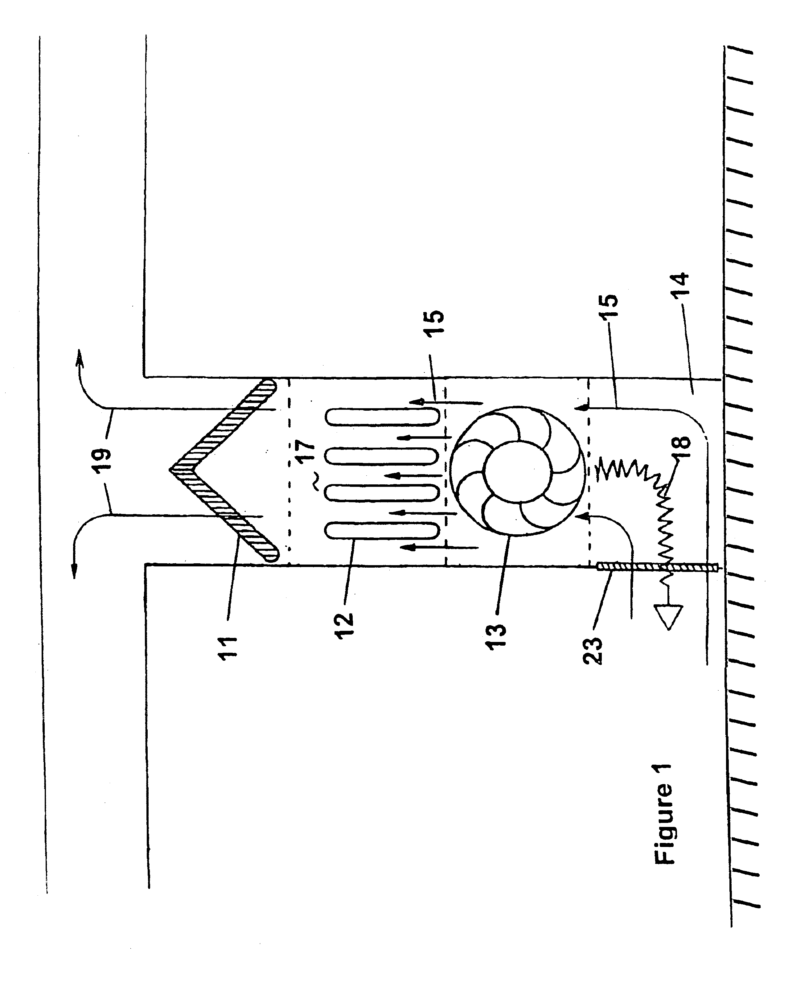
[0037]A general layout of a household HVAC heat exchange system is shown in FIG. 1. The HVAC syst...


PUM


Abstract

An acoustic attenuator includes an intake air duct having an intake air duct opening leading to an outside environment and a blower fan opening leading to a blower fan. Air is drawn through the intake air duct opening towards the blower fan and a primary reflecting panel disposed in the intake air duct. The primary reflecting panel is configured to reflect sound propagated from the blower fan away from the intake air duct opening.

Description

[0001]This is a Continuation of application Ser. No. 09 / 875,792, filed Jun. 6, 2001 now U.S. Pat. No. 6,668,970, which is hereby incorporated by reference.FIELD OF THE INVENTION[0002]This invention relates to acoustics. More specifically, reducing sound in an HVAC system is disclosed:BACKGROUND OF THE INVENTION[0003]Mechanical air control equipment of a Heating Ventilation and Air Conditioning (HVAC) system can be a major source of sound in a building. The sound generated by the HVAC system travels both upstream and downstream in the intake air duct and exhaust air duct, respectively. Various sound sources within the duct include blower fans, diffusers, airflow regulating valves, etc. Noise generated by the blower fans is of broad band frequency, typically ranging from about 200 Hz through the rest of the frequency range of human hearing. Therefore, noise generated by HVAC system, when travelling upstream through the very short intake air duct, exits the intake air filter and enters...

Claims


Application Information

Patent Timeline
IPC IPC(8): E04F17/04E04F17/00F24F13/00F24F13/24F24F7/013
CPCE04F17/04F24F13/24F24F7/013Y10S454/906
Inventor LEE, PENG
Owner ACOUSTIC HORIZONS
Why Eureka
Try Eureka