Electro-optical device and driving method for the same
a technology of optical devices and driving methods, applied in the field of display and driving systems, can solve the problems of insufficient off-off action of tfts, and cannot be expected to achieve high yield in such a situation, so as to reduce the photosensitivity of transistors and eliminate the undesirable influence of incident light
- Summary
- Abstract
- Description
- Claims
- Application Information
AI Technical Summary
Benefits of technology
Problems solved by technology
Method used
Image
Examples
first embodiment
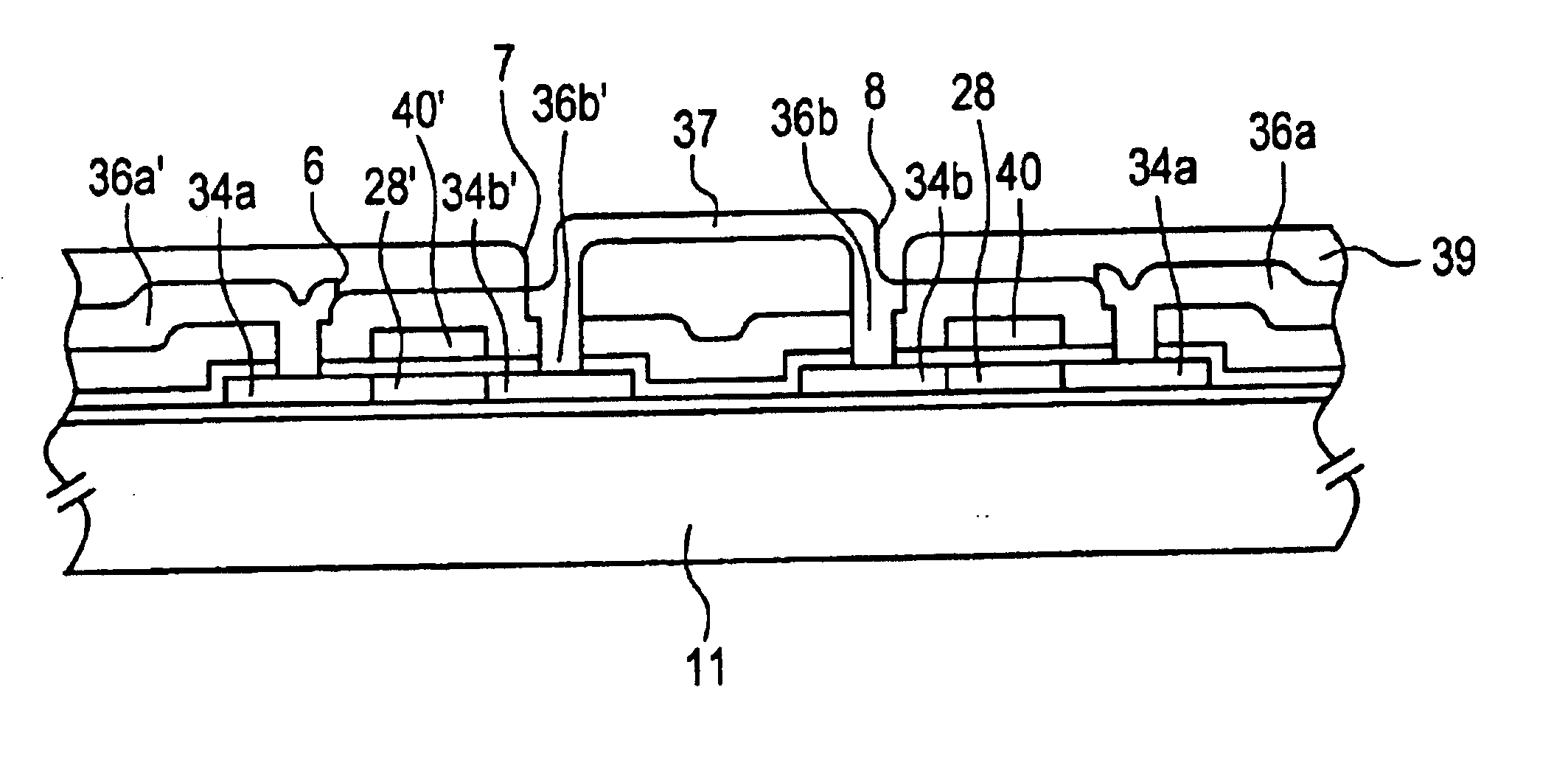
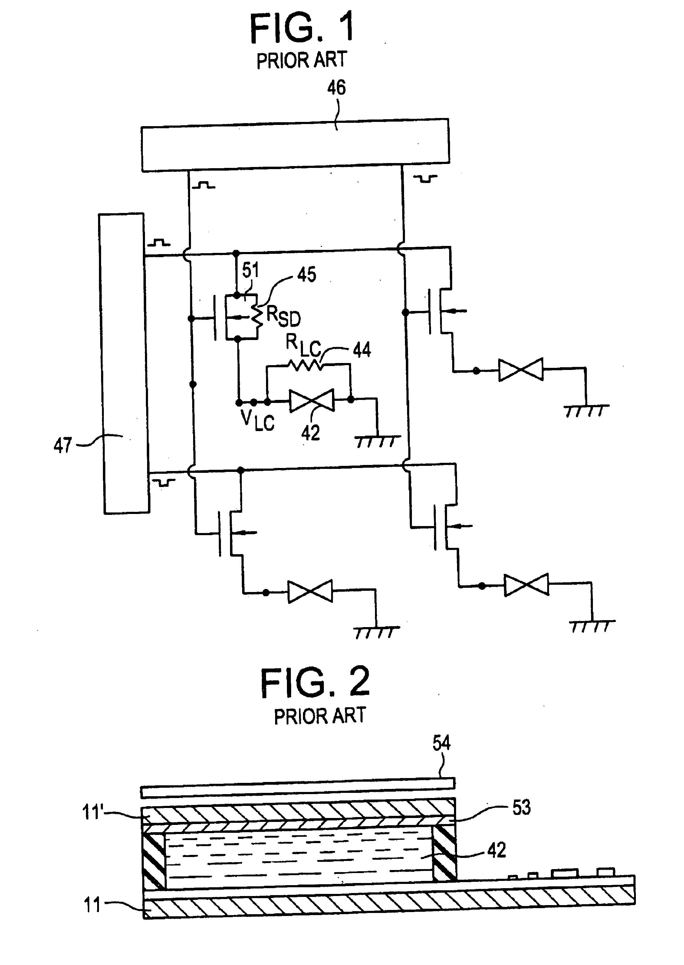
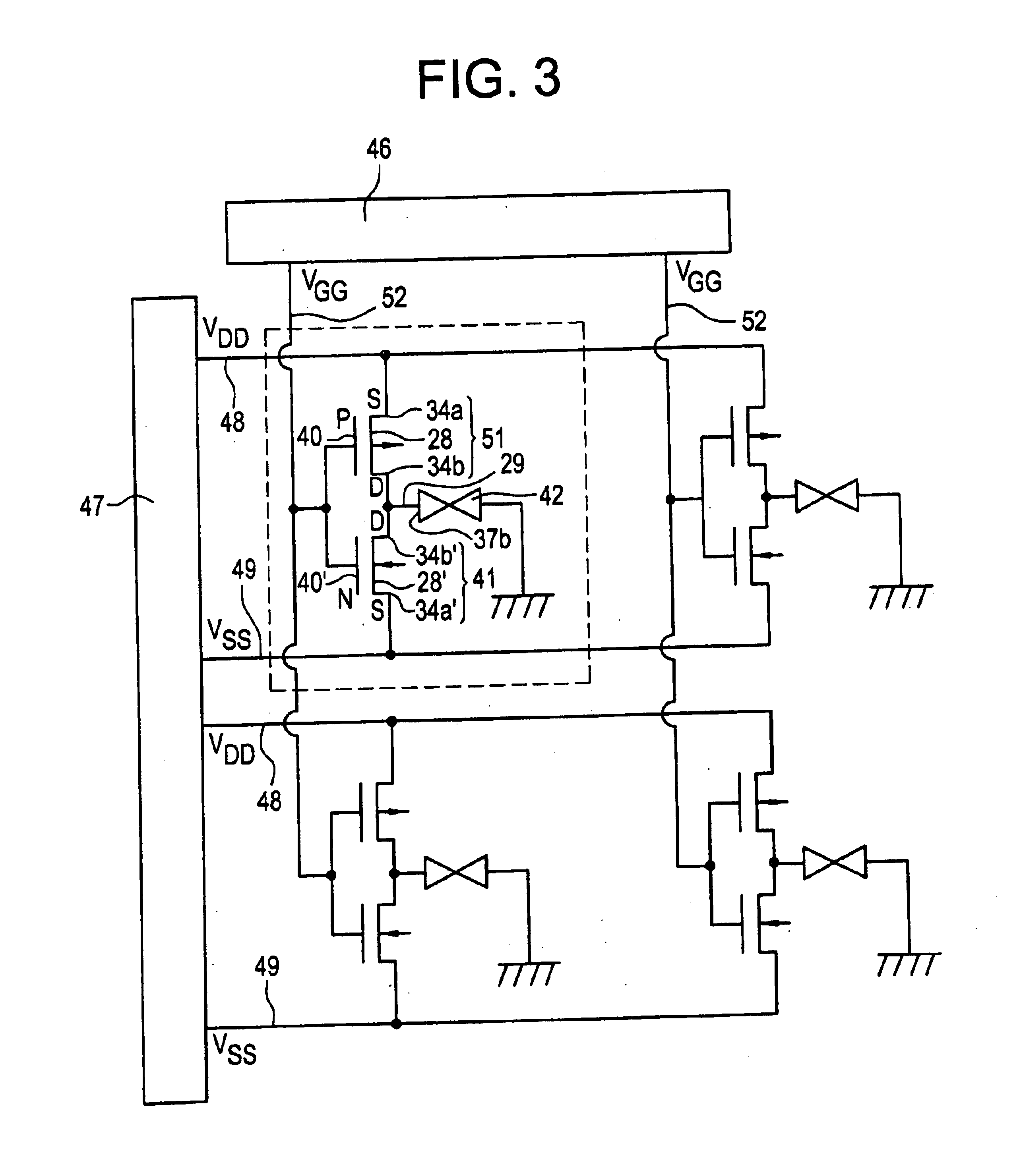
[0036]FIG. 3 is a diagram illustrating the equivalent circuit of a liquid crystal display in accordance with the present invention. The diagram shows only a 2×2 matrix for the sake of convenience in description whereas ordinary liquid crystal displays consist of more great numbers of pixels such as a 640×480 matrix, a 1260×960 matrix. The liquid crystal display includes a liquid crystal layer 42 disposed between a pair of glass substrates 11 and 11′ as shown in FIG. 2. The inner surface of the glass substrate 11′ is coated with an electrode 53. The inner surface of the other substrate 11 is provided with a plurality of conductive pads 37b each constituting one pixel of the display as seen from FIG. 4(A). Dashed line is enclosing one pixel in the figure. Each conductive pad 37b are formed on the substrate together with CMOS transistors consisting of an N-type FET 41 and a P-type FET 51 whose drains 34b′ and 34b are electrically connected with the corresponding pad 37b. The sources of...
fourth embodiment
[0064]The representative example of the driving method in accordance with the present invention will be explained with reference to FIGS. 13 and 14. In FIG. 14, the 2×2 matrix of FIG. 11 is expanded to a 4×4 matrix. The configurations of them, however, are substantially indentical except the number of pixels. FIG. 13 illustrates the control signals applied to the VDD lines, the VSS lines, the VGG lines and the back electrode. The VDD lines are called X1a, X2a, X3a and X4a from the first row to the forth row in the diagram whereas the VSS lines are called X1b, X2b, X3b and X4b in the same manner. The signals applied to the VSS lines are exactly the inversion of the signals to the VDD line as shown in FIG. 12 and therefore the waveforms of the VSS lines are dispensed with. The VGG lines are called Y1, Y2, Y3 and Y4 from the left column to the right column. In this driving method, the control signals applied to the VDD and VSS lines are addressing signals which scan from the first row ...
PUM
 Abstract
Description
Claims
Application Information
 - R&D
- Intellectual Property
- Life Sciences
- Materials
- Tech Scout
- Unparalleled Data Quality
- Higher Quality Content
- 60% Fewer Hallucinations
Browse by: Latest US Patents, China's latest patents, Technical Efficacy Thesaurus, Application Domain, Technology Topic, Popular Technical Reports.
© 2025 PatSnap. All rights reserved.Legal|Privacy policy|Modern Slavery Act Transparency Statement|Sitemap|About US| Contact US: help@patsnap.com


