Wheel rotation detecting device

a detection device and wheel technology, applied in the direction of vibration measurement in solids, axle units, machine part testing, etc., can solve the problems of unfavorable increase in and achieve the effects of increasing the weight and assembly space of the car, enhancing the detection accuracy, and increasing the manufacturing cost of the car

Inactive Publication Date: 2005-05-17
NSK LTD
View PDF20 Cites 43 Cited by
  • Summary
  • Abstract
  • Description
  • Claims
  • Application Information

AI Technical Summary

Benefits of technology

[0022]Moreover, since the second sensor is disposed within a holder holding the rotation detecting sensor therein, there is no possibility that the second sensor may increase the weight and assembling space of the wheel supporting rolling bearing unit portion and may increase the number of assembling man-hour to thereby increase the manufacturing cost of a car unfavorably. Also, in cas

Problems solved by technology

However, in case where these sensors are assembled independently of the rotation detecting sensor, the weight and assembling space of the wheel suppor

Method used


Image

  • Wheel rotation detecting device
  • Wheel rotation detecting device
  • Wheel rotation detecting device

Examples


first embodiment

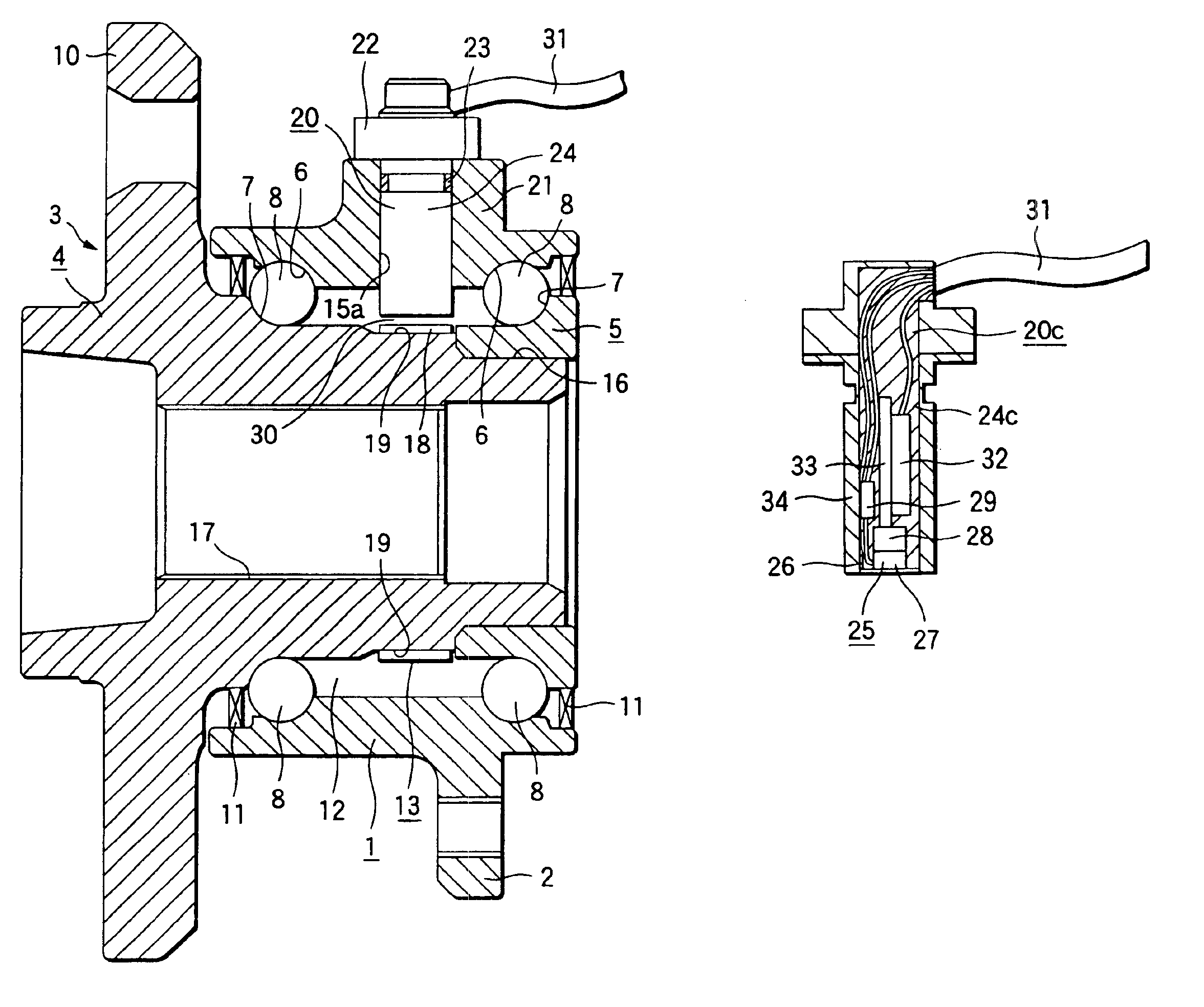
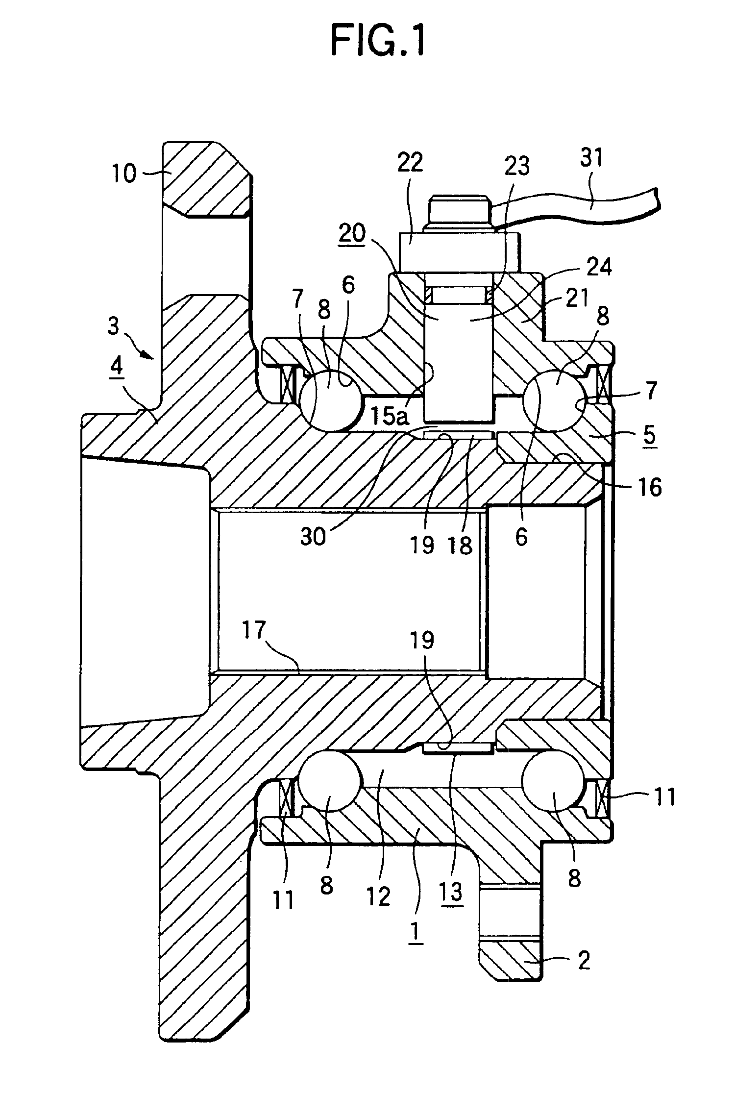
[0042]Now, FIGS. 1 and 2 shows a first embodiment according to the invention. In the first embodiment, a hub 4 formed in a hollow cylindrical shape has a flange 10 on the outer peripheral surface of the outer end portion thereof. A wheel and a disk rotor forming a brake device are fixed to a flange 10 by a plurality of studs (not shown). On the outer peripheral surface of the middle portion of the hub 4, there is formed an outside inner ring raceway 7, while an inner ring 5 including an inside inner ring raceway 7 on the outer peripheral surface thereof is fitted into and fixed to the outer portion of a stepped portion 16 provided on the inner end portion of the hub 4, thereby forming a rotary ring 3. A spline hole 17 is formed in the central portion of the hub 4 forming the thus-structured rotary ring 3; and, in an assembling state of a car, a spline shaft attached to a constant velocity universal joint (not shown) is inserted into the spline hole 17.

[0043]On the other hand, on the...

second embodiment

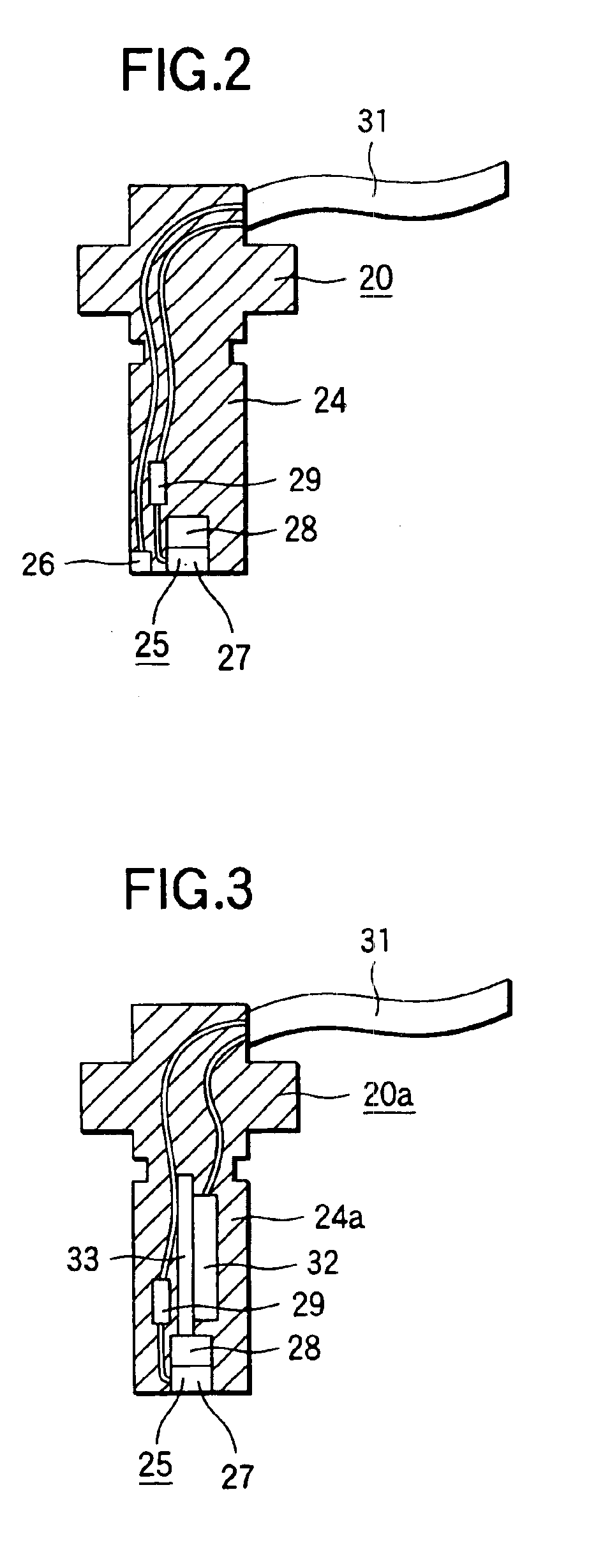
[0052]Next, FIG. 3 shows a second embodiment according to the invention. Specifically, a sensor unit 20a employed in the present embodiment comprises, within a holder 24a formed of synthetic resin, not only a magnet detect element 27, a permanent magnet 28, and a waveform shaping circuit 29 respectively used to form a rotation detecting sensor 25 but also a vibration sensor 32 which is used as a second sensor, while these components are respectively embedded in and supported by the holder 24a. The vibration sensor 32 is structured such that, for example, a small-sized acceleration sensor using a piezoelectric element and a signal processing circuit are mounted on a substrate 33 and, in this state, they are molded into the holder 24a. Referring to the position of the vibration sensor 32, in order to be able to make the sensor unit 20a compact as a whole, preferably, as shown in FIG. 3, with respect to the axial direction (in FIG. 3, the vertical direction) of the holder 24a, the vibr...

fifth embodiment

[0062]Next, FIGS. 9 and 10 show a fifth embodiment according to the invention. In the present embodiment, as an encoder 13a which is fitted with and fixed to the outer portion of the hub 4 in order to detect the rotation speed of the hub 4, there is used an encoder made of a permanent magnet. This encoder 13a can be formed such that an encoder main body made of a rubber magnet including ferrite powder or rare earth system magnet powder mixed therein is attached to the whole of the outer peripheral surface of a cylindrical-shaped core. The encoder main body may also be made of a plastic magnet or a bonded magnet. Also, the core may be formed of metal or synthetic resin. More preferably, the core may be made of a magnetic metal plate such as a steel plate, because the intensity of magnetic flux generated from the outer peripheral surface of the encoder main body can be increased: that is, even in case where the minute clearance 30 between the outer peripheral surface of the encoder ma...


PUM


Abstract

A wheel rotation detecting device including a sensor unit that is supported on a stationary ring which does not rotate even when the wheel is in use, and the rotation of the wheel that is attached to a rotary ring can be detected by a rotation detecting sensor held within the sensor unit. Within the sensor unit, in addition to a rotation detecting sensor, there are disposed other sensors such as a temperature sensor and a vibration sensor, thereby allowing detection of the rotation speed and the rotation number of the wheel supported on the rotary ring, as well as detection of other car driving conditions.

Description

BACKGROUND OF THE INVENTION[0001]1. Field of the Invention[0002]The present invention relates to a wheel rotation detecting device which detects the rotation speed (or rotation number) of a wheel of a car supported on a suspension and also detects the conditions of a rolling bearing unit portion supporting the wheel of the car, such as the temperature or vibration thereof.[0003]2. Description of the Related Art[0004]To obtain the rotation speed of a wheel in order to be able to control an antilock brake system (ABS) or a traction control system (TCS), in the related art, there are known various kinds of wheel supporting rolling bearing units with a rotation speed detecting device each structured such that a rotation speed detecting device is incorporated into a rolling bearing unit used to support the wheel on a suspension of a car. Here, as an example of a wheel supporting rolling bearing unit with a rotation speed detecting device which is used for the above purpose, FIG. 19 shows...

Claims


Application Information

Patent Timeline
IPC IPC(8): B60T8/171B60T8/32B60T8/17G01P3/42G01P3/44G01D21/02G01P3/488B60B35/18F16C19/18F16C19/52F16C41/00G01K1/14G01K13/08
CPCB60T8/171B60T8/329F16C19/186F16C19/525G01M13/045G01P3/446F16C41/007G01D21/02F16C2326/02F16C19/527
Inventor TAKIZAWA, TAKESHIENDO, SHIGERUSAKATANI, IKUNORIMOMONO, TATSUNOBUMUTOH, YASUSHI
Owner NSK LTD
Why Eureka
Try Eureka