Battery grids

a battery grid and positive plate technology, applied in the field of leadacid batteries, can solve the problems of end the useful life or life cycle of the battery, limit the design or pattern of the wire and the grids of the positive plate are subject to far more corrosion and growth than the grids, so as to reduce the thickness of the web, and reduce the effect of thickness

Inactive Publication Date: 2005-05-24
WIRTZ MFG CO INC
View PDF13 Cites 10 Cited by
  • Summary
  • Abstract
  • Description
  • Claims
  • Application Information

AI Technical Summary

Benefits of technology

[0009]Preferably, the positive and negative grids are made by continuous casting an elongate web of a plurality of grid blanks, preferably washing the web to remove molding compounds, and then passing the web through the nip of one or more pairs of compression rollers to reduce the thickness of the web. The thickness of the web is usually reduced within 24 hours, desirably within 12 hours, preferably within 4 hours and more preferably right after being continuously cast and washed or cleaned. This reduction in thickness also significantly increases the length of the web and grid wires extending parallel to the direction of travel of the web through the rollers and substantially increases the width of the grid wires extending transversely to the direction of travel of the web through the rollers. After the reduction is completed, the web is pasted, preferably cut into wet pasted grids or plates, dried to remove moisture and at least begin curin

Problems solved by technology

In use, in lead-acid batteries, the lead grids of the positive plates are subject to far more corrosion and growth than are the grids of the negative plates.
In use, the lead in the positive plates corrodes or erodes away and disappears which decreases and eventually ends the useful life or life cycle of the battery.
This tends to cause the positive grid plates to pierce their separators or envelopes and short or ground out with an adjacent negative plate.
This growth also tends to limit the design or pattern of the wires of the positive grids because diagonal wires are longer and hence have a greater absolute increase in length and hence a greater tendency to pierce a separator and short out.
It has been found that compared to book molded grids, when continuous cast grids are utilized in positive plates, they are subject to greater growth and significantly increased corrosion which results in a useful life

Method used


Image

  • Battery grids
  • Battery grids
  • Battery grids

Examples


Embodiment Construction

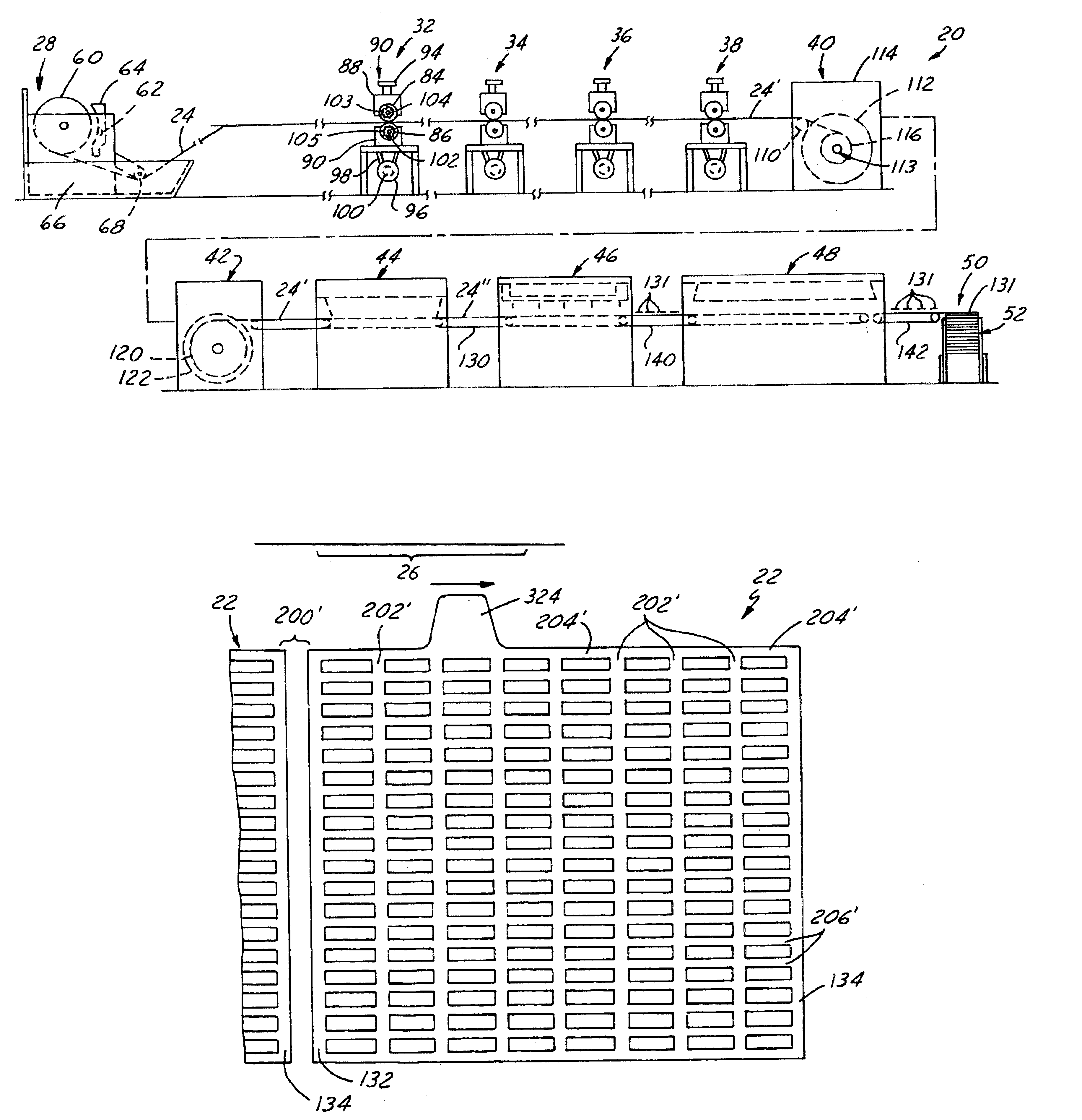
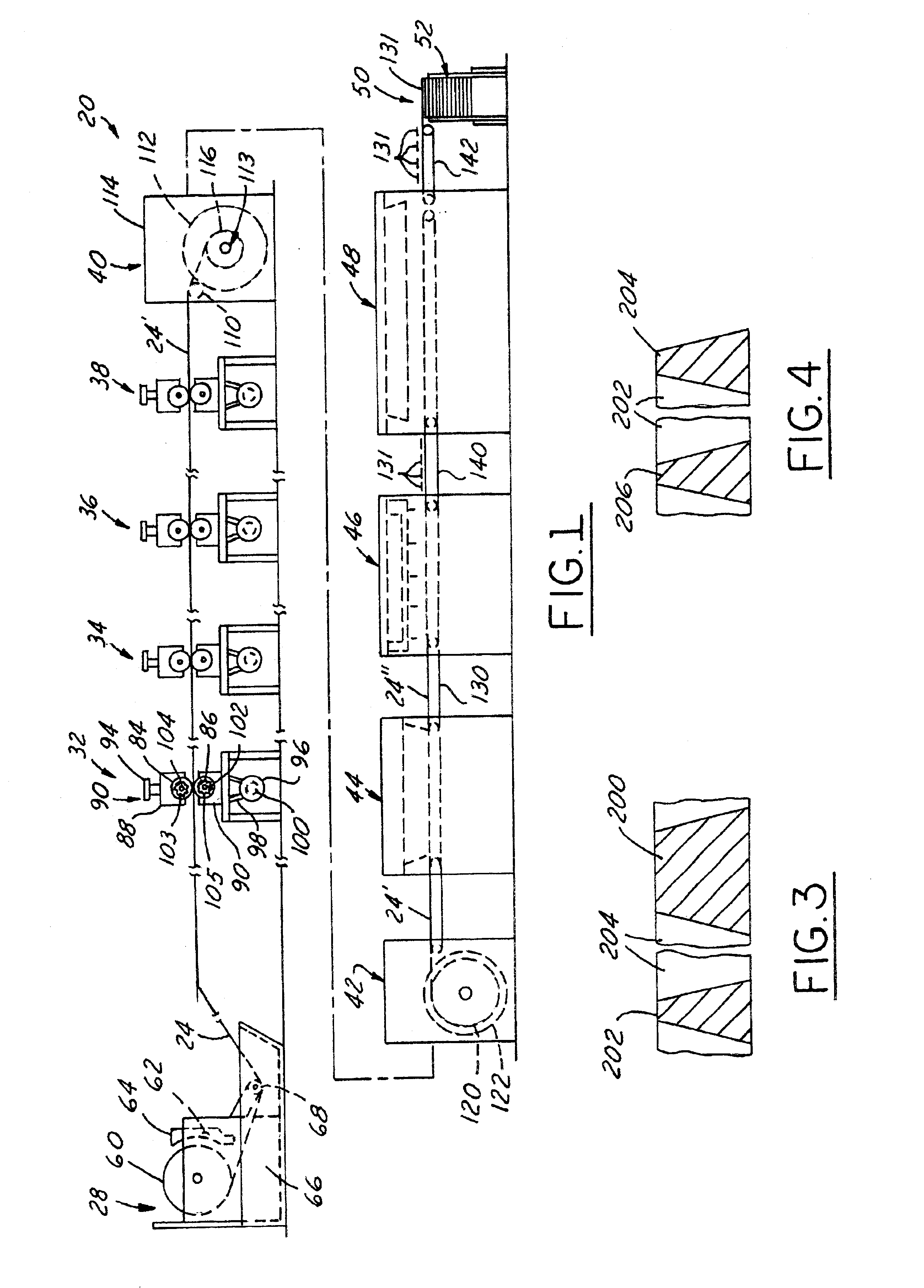
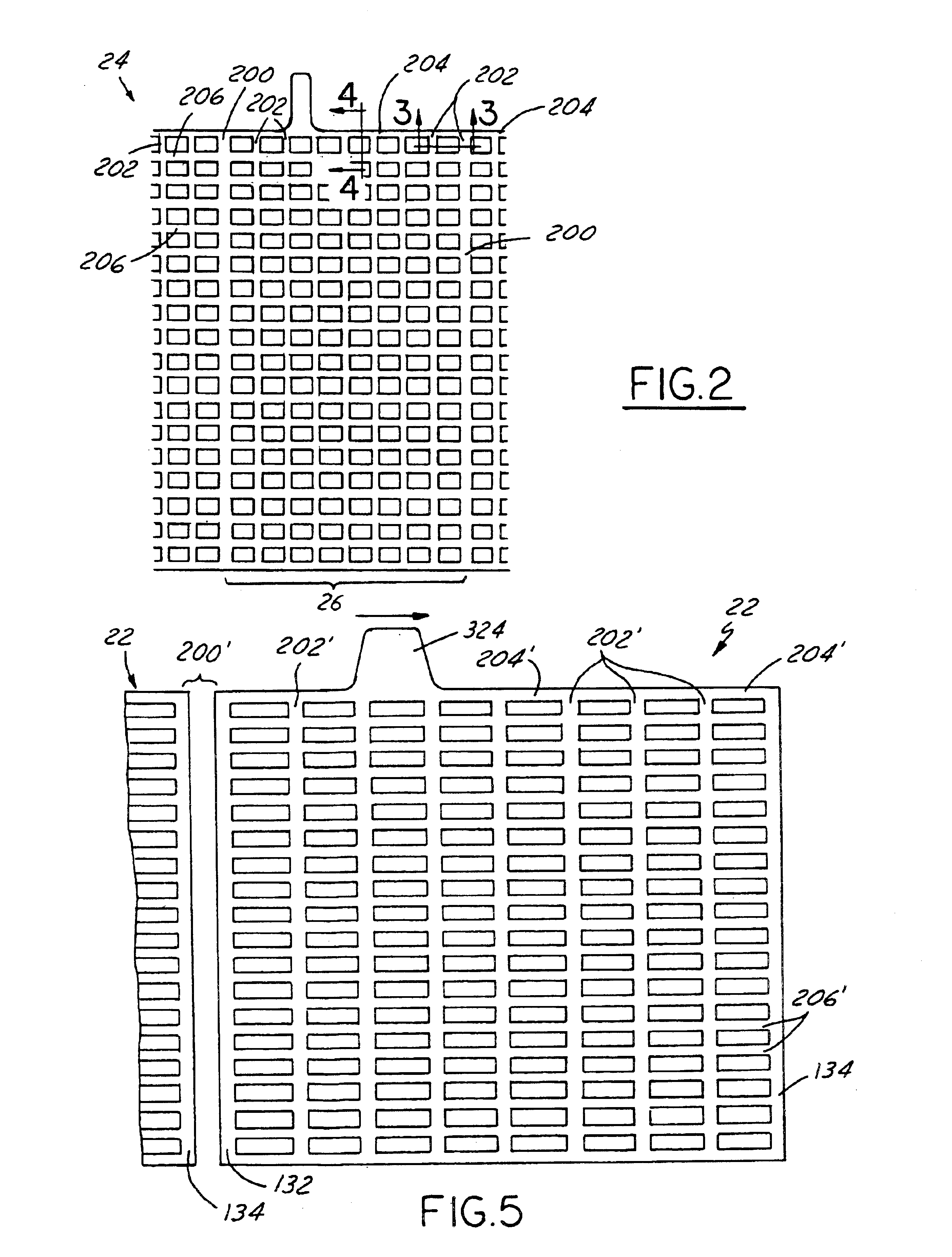
[0020]Referring in more detail to the drawings, FIG. 1 illustrates a production line 20 for utilizing the method of this invention to make battery positive grids 22 (FIG. 5) and negative grids 23 (FIG. 7), and battery plates or electrodes of this invention. In the production line, a web 24 of a plurality of interconnected successive grid blanks is continuously cast from a molten lead composition by a continuous casting machine 28. The moving web 24 is reduced in cross section and elongated in the direction of travel by a series of compression roller machines 32, 34, 36&38 and wound on a drum or reel in a coiling machine 40 for inspection, handling and any storage before further processing. The web is unwound from the reel in an uncoiling machine 42, passes through a continuous pasting machine 44, which applies battery paste to the web and a cutting machine 46 which cuts individual pasted grids or plates from the web. The individual pasted plates pass in succession through a drying o...


PUM

PropertyMeasurementUnit
Fractionaaaaaaaaaa
Timeaaaaaaaaaa
Timeaaaaaaaaaa

Abstract

A battery positive grid is continuously cast of lead and thereafter cold worked to reduce its cross sectional thickness to change the microstructure of the lead and provide enhanced corrosion resistance and other properties needed for positive grids. The as cast thickness is reduced by not more than ½ or 2 to 1, to produce a positive grid with a lead weight of 0.5 to 2.1 grams per square inch of the area of the plan of the cold worked grid which improves the life of a battery in which it is used. A battery negative grid is continuously cast of lead and thereafter cold worked to reduce its cross sectional thickness 1.2:1 to less then 1.5:1 to increase the ultimate tensile strength needed for a lighter negative grid with a lead weight of 0.3 to 0.9 of a gram per square inch of the area of its plan.

Description

REFERENCE TO COPENDING APPLICATION[0001]This application is a continuation-in-part of U.S. patent application Ser. No. 09 / 364,639, filed on Jul. 30, 1999, and now abandoned.FIELD OF THE INVENTION[0002]This invention relates to lead-acid batteries and more particularly to cast grids for these batteries and a method and apparatus of making continuously cast grids.BACKGROUND OF THE INVENTION[0003]In use, in lead-acid batteries, the lead grids of the positive plates are subject to far more corrosion and growth than are the grids of the negative plates. In use, the lead in the positive plates corrodes or erodes away and disappears which decreases and eventually ends the useful life or life cycle of the battery. In use, the lead grids of the positive plates also grow and expand or elongate, particularly in length and height, on the order of 5% to 15% of their original length and height. This tends to cause the positive grid plates to pierce their separators or envelopes and short or groun...

Claims


Application Information

Patent Timeline
IPC IPC(8): H01M4/72H01M4/73H01M4/14H01M4/84H01M10/14
CPCH01M4/73Y10T29/10Y02E60/126Y02E60/10Y02P70/50H01M4/72
Inventor WIRTZ, JOHN O.
Owner WIRTZ MFG CO INC
Why Eureka
Try Eureka