
Two-cycle combustion engine having two-staged piston

a two-stage piston and combustion engine technology, applied in the direction of combustion engine, machine/engine, fuel air intake, etc., can solve the problems of inability to completely eliminate the increase in cost, and complication in structure, so as to achieve the effect of avoiding the undesirable blow-off phenomenon of the air-fuel mixture and simple structur

Inactive Publication Date: 2005-05-24
KAWASAKI HEAVY IND LTD
View PDF5 Cites 2 Cited by
  • Summary
  • Abstract
  • Description
  • Claims
  • Application Information

AI Technical Summary

Benefits of technology

[0009]In view of the foregoing, the present invention has been devised to provide an improved two-cycle combustion engine of a kind having a two-staged piston, which is simple in structure and inexpensive and in which the undesirable blow-off phenomenon of the air-fuel mixture can be avoided effectively.

Problems solved by technology

Accordingly, the conventional two-cycle combustion engine is susceptible to a problem in that a portion of the air-fuel mixture supplied into the combustion chamber tends to flow outwardly through an exhaust port together with the combustion gas, that is, susceptible to a so-called blow-off phenomenon.
It has, however, been found that the first mentioned two-cycle combustion engine disclosed in the Japanese Laid-open Patent Publication No. 5-118225 has a problem in that it requires a mechanism for driving the intake valve for selectively opening or closing the intake port, through which the air-fuel mixture can be introduced into the combustion chamber, by means of a cam shaft or a crankshaft.
In addition, the first mentioned two-cycle combustion engine requires a carburetor for supplying the air-fuel mixture into the pump chamber, an air cleaner for supplying an air into the crank chamber and the intake valve for selectively opening or closing the intake port through which the air-fuel mixture can be supplied from the pump chamber into the combustion chamber to be disposed having been spaced a distance from each other, resulting in complication in structure and increase in cost.
Yet, since the air-fuel mixture is introduced into the combustion chamber during opening of the intake valve prior to the exhaust port being completely closed, it is not possible to completely eliminate the blow-off phenomenon of the air-fuel mixture.
On the other hand, the second mentioned two-cycle combustion engine disclosed in the Japanese Examined Patent Publication No. 57-45890 has a problem in that since the air-fuel mixture once discharged into the exhaust passage through the exhaust port is forced to return into the cylinder bore by the action of the air injected through the injection nozzle, the efficiency with which the blow-off phenomenon can be effectively prevented is low and, also, since a large amount of air and a high air pressure are necessary, the auxiliary chamber tends to increase in size.
For these reasons, even in this two-cycle combustion engine, the blow-off phenomenon of the air-fuel mixture cannot be avoided effectively.

Method used


Image

  • Two-cycle combustion engine having two-staged piston
  • Two-cycle combustion engine having two-staged piston
  • Two-cycle combustion engine having two-staged piston

Examples


first embodiment

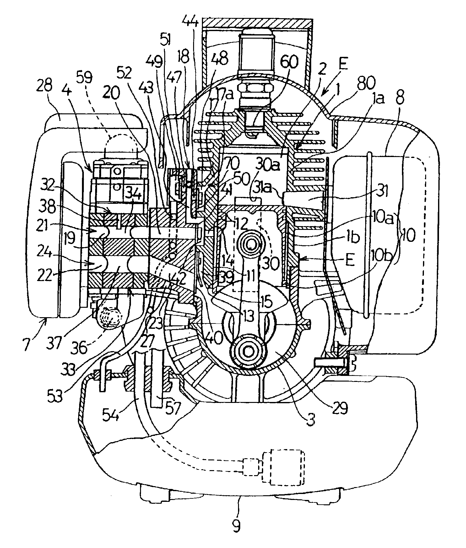
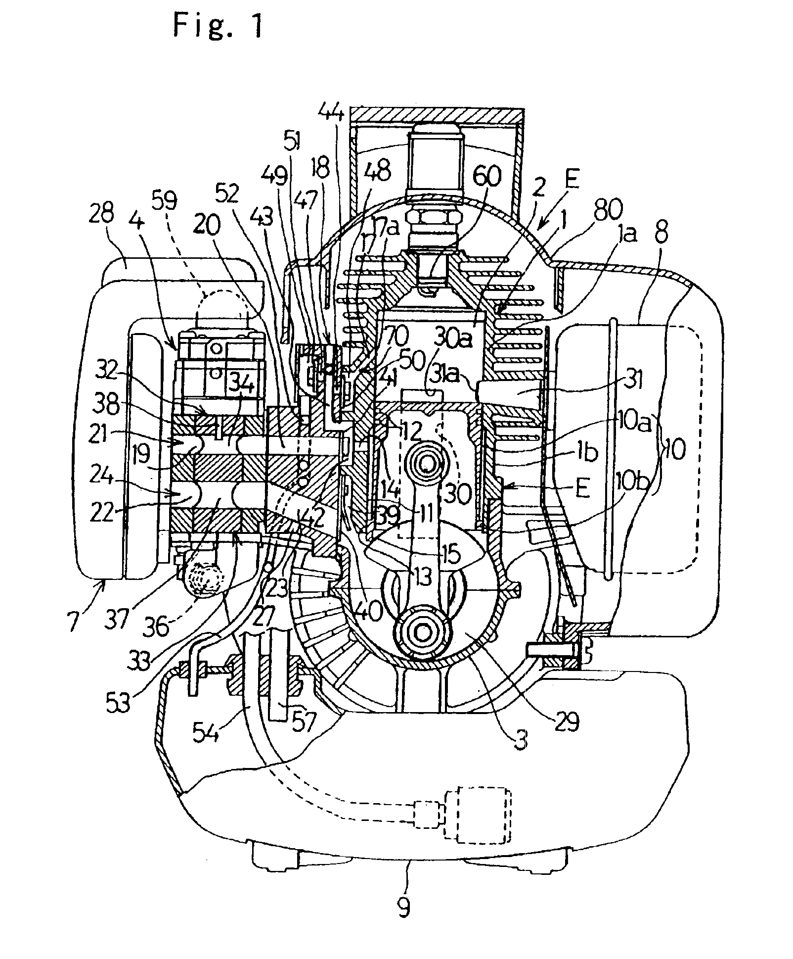
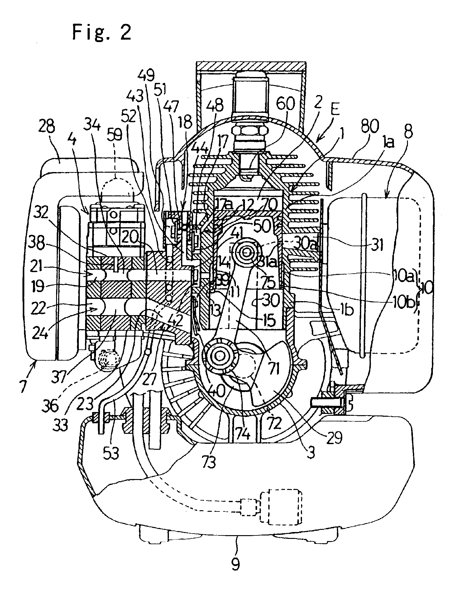
[0047]As hereinabove described, with the two-cycle combustion engine according to the present invention, since the blow-off phenomenon of the air-fuel mixture which would otherwise occur during each of the compression stroke, in which the two-staged piston 10 ascends, and the scavenge stroke in which the two-staged piston 10 descends can advantageously be avoided, fuel consumption is low. Also, in addition to the effect of reducing the concentration of the HC exhaust gas, the following advantages can also be appreciated. Specifically, the carburetor 4 includes, in addition to the air-fuel mixture supply port 19 forming a part of the air-fuel mixture passage 21, the air supply port 22 forming a part of the air passage 24 and, on the other hand, the respective openings of the intake port 34 and the air port 37 relative to the air-fuel mixture passage 21 and the air passage 24 can be adjusted as the single rotary valve 32 is rotated during the operation of the combustion engine so that...

second embodiment

[0053]It is to be noted that although in the present invention the two injection passages 70A and 70B have been employed, the number of the injection passages may not be always limited to two such as shown and described and only one or more injection passage may be employed within the broad aspect of the present invention.

[0054]FIG. 7 illustrates a third preferred embodiment of the present invention. In this third embodiment, the structure necessary to relieve the pressure inside the connecting passage 43 communicated with the second valve chamber 42 to which the air-fuel mixture is supplied differs from that employed in any one of the first and second embodiments. More specifically, in any one of the first and second embodiments shown in and described with reference to FIGS. 1 to 3 and FIGS. 5 and 6, respectively, when the injection port 17a shown in FIG. 2 is closed as a result of the ascend of the two-staged piston 10 with the pressure of the air-fuel mixture inside the connectin...


PUM


Abstract

A two-cycle combustion engine with a two-staged piston addresses a blow-off phenomenon of an air-fuel mixture. A cylinder block has a two-staged cylinder bore with a reduced diameter bore portion and a large diameter bore portion, and a two-staged piston having a reduced diameter piston portion and a large diameter piston portion. An annular auxiliary chamber is defined between the cylinder bore and the two-staged piston. An air passage introduces air mixed with oil into a crank chamber. An air-fuel mixture passage introduces the air-fuel mixture into the auxiliary chamber. A scavenge air passage supplies the air within the crank chamber into a combustion chamber, and an injection passage injects the air-fuel mixture within the auxiliary chamber into the combustion chamber from an inner peripheral surface of the cylinder block in a direction oriented substantially diagonally upwardly.

Description

BACKGROUND OF THE INVENTION[0001]1. Field of the Invention[0002]The present invention generally relates to a two-cycle combustion engine of an air scavenging type suitable for use as a power plant for a compact rotary machine such as, for example, a brush cutter and, more particularly, to the two-cycle combustion engine of a kind wherein a two-staged piston is drivingly inserted in a correspondingly two-staged cylinder bore.[0003]2. Description of the Related Art[0004]The two-cycle combustion engine is generally of a design in which an air-fuel mixture introduced into a crank chamber is supplied into a combustion chamber to scavenge a combustion gas within the combustion chamber. Accordingly, the conventional two-cycle combustion engine is susceptible to a problem in that a portion of the air-fuel mixture supplied into the combustion chamber tends to flow outwardly through an exhaust port together with the combustion gas, that is, susceptible to a so-called blow-off phenomenon. In v...

Claims


Application Information

Patent Timeline
Patent Type & Authority Patents(United States)
IPC IPC(8): F02B75/16F02F1/22F02B63/02F02B33/04F02B25/00F02B33/02F02B25/22F02M71/00F02M71/02F02B75/00F02F1/18F02B63/00F02B33/14F02B1/04F02B1/00F02B75/02F02M35/104F02M35/10F02M35/108F02B23/08F02B25/20F02F3/00
CPCF02B25/22F02B33/04F02B63/02F02F1/22F02M35/1019F02M71/02F02B75/16F02B1/04F02B33/14Y02T10/14F02B2075/025F02M35/108Y02T10/12
Inventor YUASA, TSUNEYOSHIYAMANE, YOSHIROKOBAYASHI, MASANORI
Owner KAWASAKI HEAVY IND LTD
Learn More