Heat exchange reactor having integral housing assembly

Inactive Publication Date: 2005-05-24
LAIR LIQUIDE SA POUR LETUDE & LEXPLOITATION DES PROCEDES GEORGES CLAUDE
View PDF15 Cites 8 Cited by
  • Summary
  • Abstract
  • Description
  • Claims
  • Application Information

AI Technical Summary

Benefits of technology

[0015]Another object of the present invention is to provide a heat exchange reactor having reduced warm-up time and energy expenditure.
[0017]Another object of the present invention is to provide an integral housing with simpler manufacture, lower materials cost, and less material usage than possible with conventional designs.
[0019]Another object of the present invention is to provide a heat exchanger and tube bundle components that may be manufactured with less scrap and simpler tooling than required in conventional systems with rounded internal pressure shells.

Problems solved by technology

First, because of the high operating temperatures of many heat exchange reactors, particularly those for steam reforming of hydrocarbons, the strength of the internal pressure shell material is greatly reduced, which requires the shell thickness to be very thick relative to similar pressure vessels operated at ambient temperatures. In addition, the pressure shell material, which is usually metallic, must be selected from those alloys that have adequate high-temperature strength and corrosion resistance for the operating conditions. This usually requires stainless steel or nickel-based alloys, which are far more expensive and difficult to fabricate than materials suitable for lower-temperature construction. The use of a thick, metallic shell is particularly disadvantageous for heat exchange reactors because the shell must be heated to the operating temperature during startup of the reactor, which considerably lengthens the startup period and increases the thermal energy required for startup.
Second, the close fit between the pressure shell and the components of the internal tube bundle such as baffles or fins requires very close manufacturing tolerances, which undesirably increases the manufacturing cost of both the pressure shell and the tube bundle. This problem is exacerbated by the fact that most pressure shells are round in planform, which requires the aforementioned baffles and fins to be manufactured with a corresponding round planform: this is difficult to manufacture using high-rate techniques (such as stamping) and is wasteful of raw materials.
Third, the round planform of typical tubular arrays and heat exchanger shells undesirably causes the formation of thermal gradients both in the direction of fluid flow across the tube bundle and normal to the direction of flow unless a chorded array of tubes is employed. A chorded array is less efficient in filling a round planform shell of a given diameter, however, which increases the ratio of shell mass to reactor mass and exacerbates the deleterious effects of the heavy reactor shell described above. In the absence of a chorded array, extreme thermal stresses will be experienced in the tube arrays, thus reducing both their useful strength and useful operational lifetime. This problem is particularly acute in reactors employing very high shell-side inlet temperatures and rapid heat exchange, which features are otherwise desirable in heat exchange reactors to minimize volume, weight and cost.
Fourth, the installation of the insulation layers around the exterior of the pressure shell exposes the insulation to mechanical damage unless a separate outer covering is employed to prevent impact damage, water damage, wind damage, or damage due to the action of vermin. This outer covering undesirably adds weight, volume and cost to the heat exchange reactor without serving any other purpose. In addition, the installation of this covering must accommodate the means of structural support of the heat exchange reactor, and must therefore often be of a complex shape to prevent the ingress of water.
Fifth, the structural supports are generally connected to the tube bundle or to the pressure shell. Because these components are generally at elevated temperature, the structural members serve as a route for substantial heat loss to the ambient through rapid heat conduction away from heat exchange reactor surface. Because the structural members are also then at elevated temperature, they are usually also constructed of expensive alloys. Finally, the heat loss to the structural support, as well as its heavy metallic construction, further increases the required energy to bring the heat exchange reactor to operating conditions beyond the already undesirable state of affairs engendered by the use of the metallic pressure shell.

Method used


Image

  • Heat exchange reactor having integral housing assembly
  • Heat exchange reactor having integral housing assembly
  • Heat exchange reactor having integral housing assembly

Examples


Embodiment Construction

[0039]Various other objects, features and attendant advantages of the present invention will be more fully appreciated as the same becomes better understood from the following detailed description of the preferred embodiments of the invention.

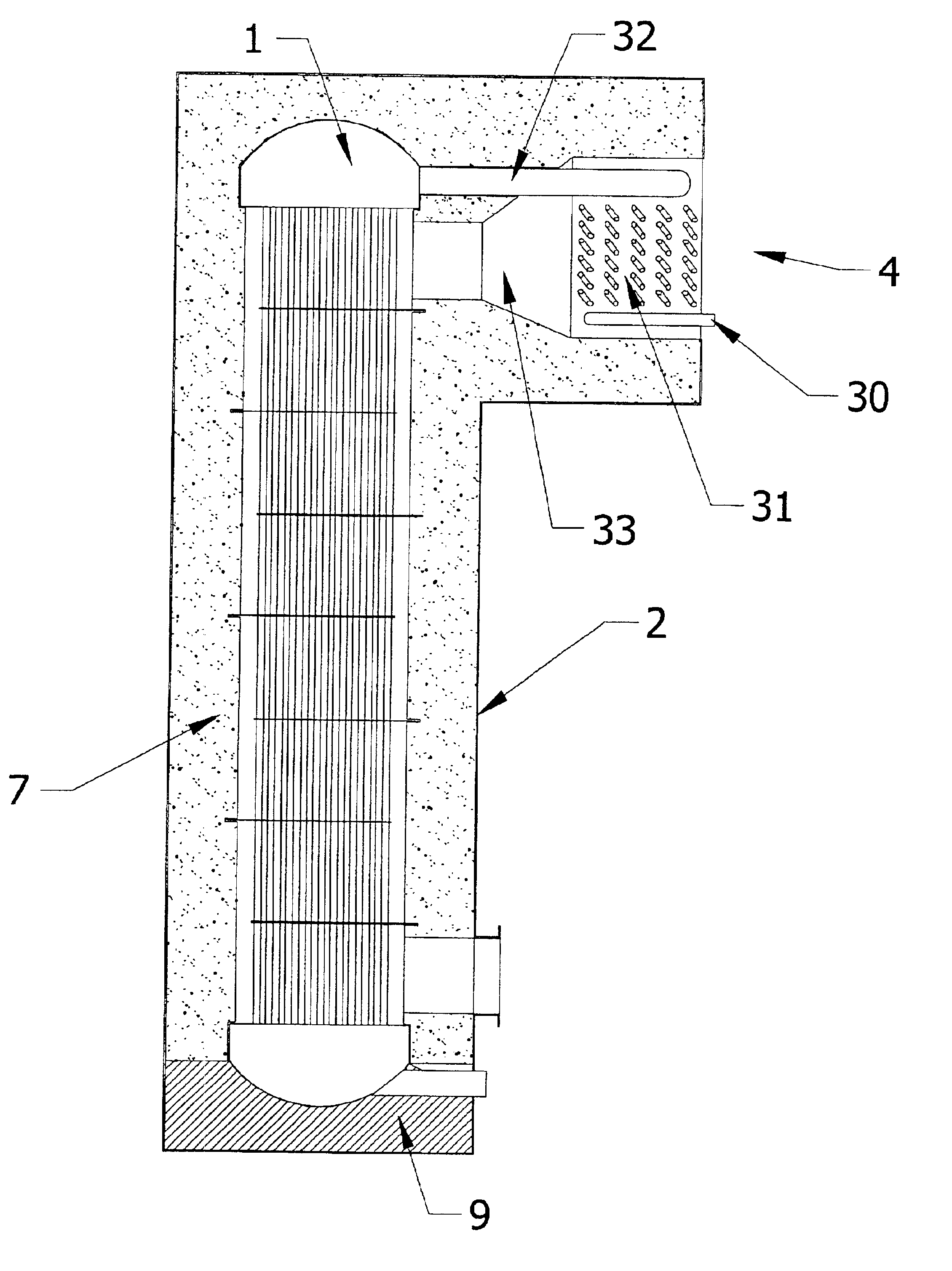
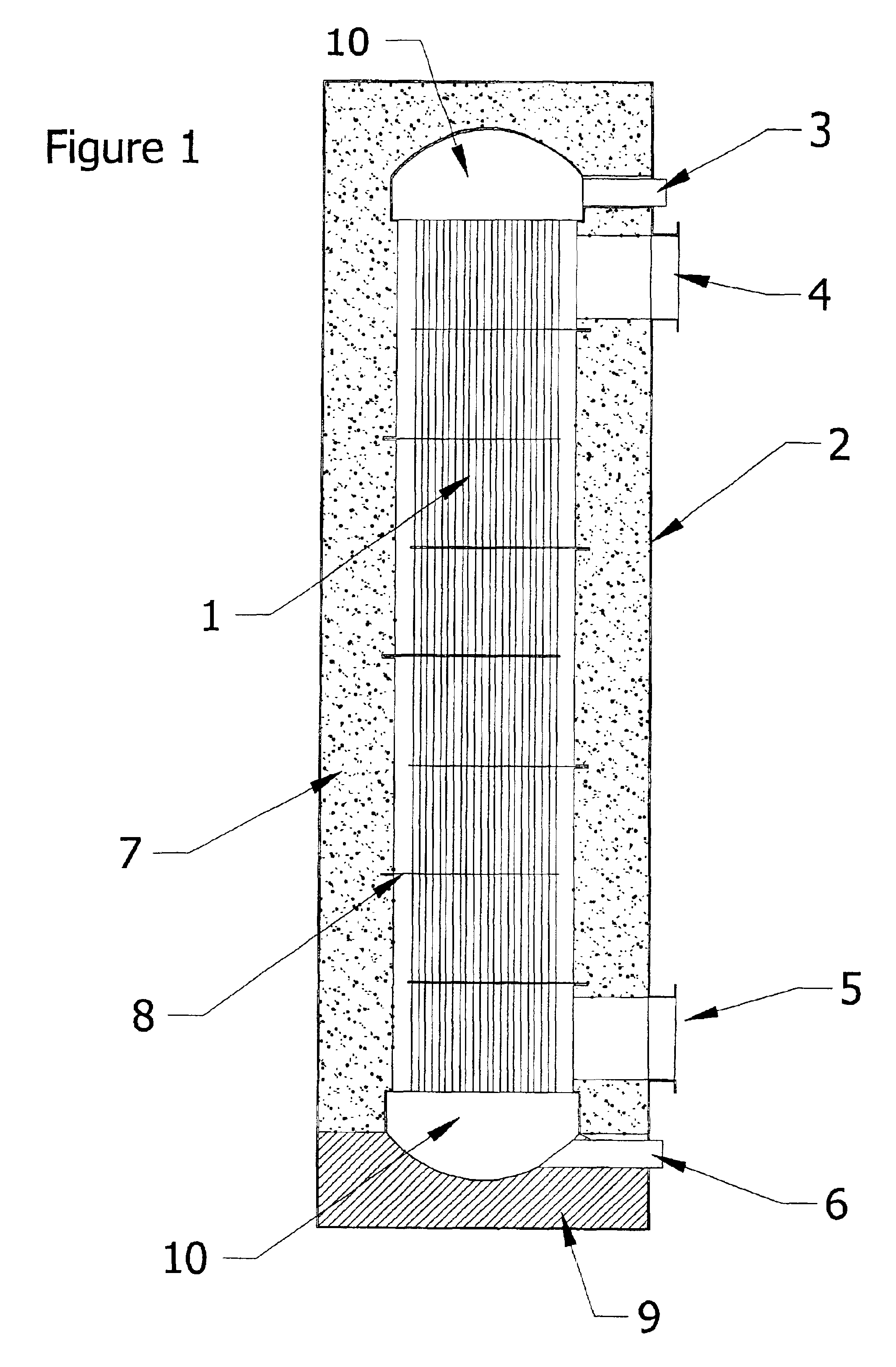
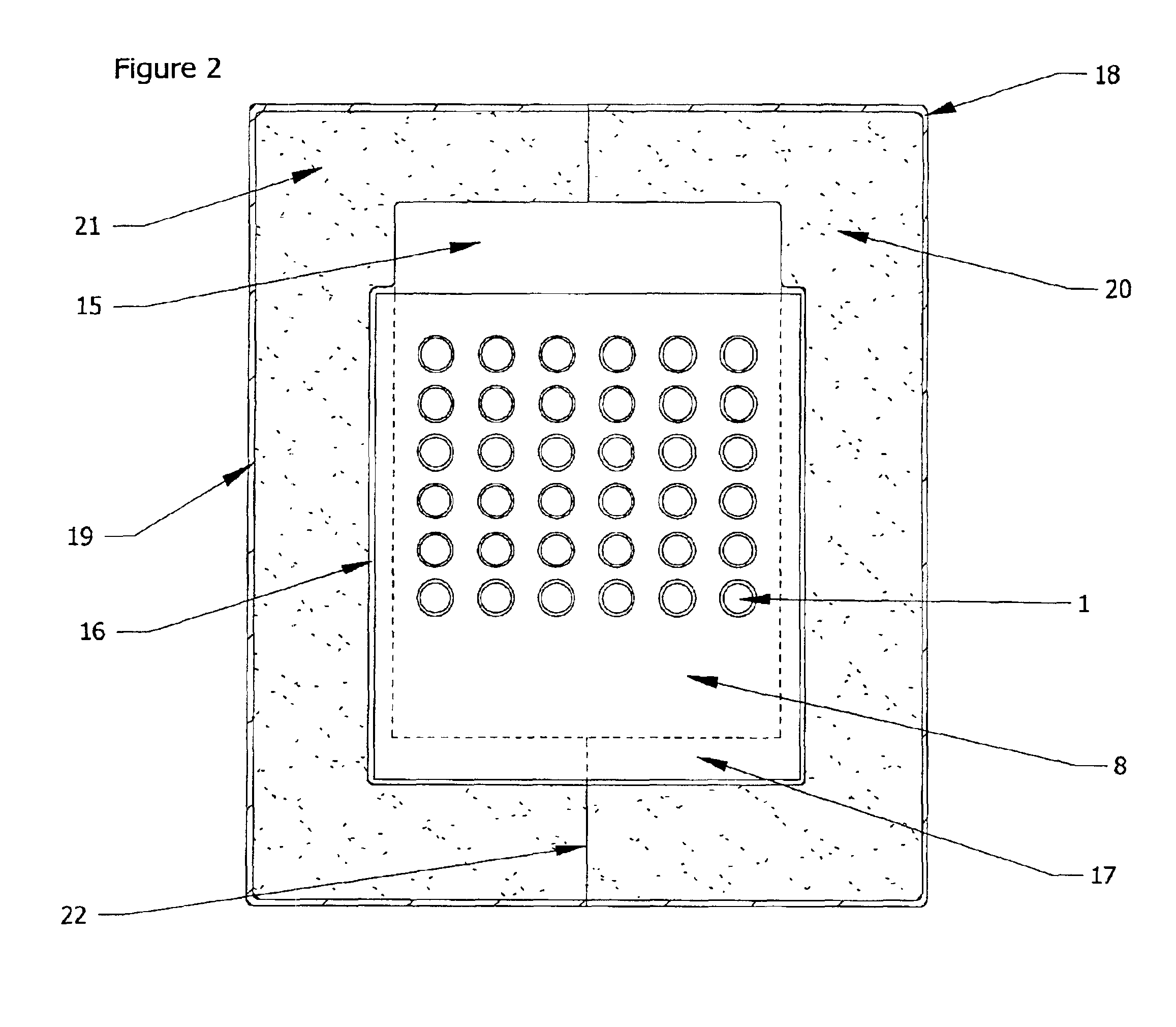
[0040]One preferred embodiment of the present invention provides an integral housing assembly for heat exchange reactors employing a tube bundle construction with internal (within the tubes or “tube-side”) flow of a first reacting fluid and the external (outside the tubes or “shell-side”) flow about the tubes of a second fluid which may be both reacting and exchanging heat with the first reacting fluid, or simply exchanging heat with the first fluid. The tube- and shell-sides are preferably not in fluid contact with one another and are preferably only in thermal contact with one another. The integral housing of the present invention preferably includes:

[0041]an external pressure housing having at least one inlet and at least one outlet for the ...


PUM


Abstract

The present invention provides a heat exchange reactor, which includes at least one tube bundle containing a plurality of tubes arranged substantially parallel to a common longitudinal axis and within an external pressure housing, the bundle having first and second ends in respective first fluid communication with at least one first fluid inlet and at least one first fluid outlet, and the external pressure housing having at least one second fluid inlet and at least one second fluid outlet; at least one baffle oriented substantially perpendicular to the longitudinal axis and disposed about the bundle and configured as a manifold to control a flow of the second fluid; at least one layer of interior thermal insulation disposed between the bundle and the housing and in fluid communication with the second fluid. Other embodiments of the present invention include methods of using and methods of making the heat exchange reactor.

Description

BACKGROUND OF THE INVENTION[0001]1. Field of the Invention[0002]The present invention relates to a heat exchange reactor having a tube-and-shell construction, methods of its manufacture, and uses thereof.[0003]2. Discussion of the Background[0004]Heat exchange reactors are employed in many chemical processes where a reacting fluid must be heated by heat exchange from a second fluid. An excellent example of such a process is the generation of hydrogen from hydrocarbon feedstocks via catalytic steam reformation. The construction of such reactor vessels often closely resembles the common shell and tube heat exchanger construction known to those skilled in the art. Shell and tube heat exchange reactors for the steam reforming reaction are sold commercially, for example, by Haldor Topsoe, of Houston, Tex. Heat exchange reactors of shell and tube construction are also used to control the temperature of the water-gas shift reaction, as described in U.S. Pat. No. 4,554,223 to Yokoyama, et a...

Claims


Application Information

Patent Timeline
IPC IPC(8): B01J19/24B01J8/02B01J8/06B01J19/00F28F9/00F28F9/22F28D7/00
CPCB01J8/067B01J19/2425F28D7/0075F28D7/1653F28F9/00F28F9/22B01J19/006F28F2270/00B01J2208/00212B01J2208/00221B01J2208/00256B01J2208/00495B01J2219/00085B01J2219/00155B01J2219/00768F28F2009/226
Inventor LOMAX, JR., FRANKLIN D.JAMES, BRIAN D.
Owner LAIR LIQUIDE SA POUR LETUDE & LEXPLOITATION DES PROCEDES GEORGES CLAUDE
Why Eureka
Try Eureka