Ultrafine-grain-copper-base sputter targets

a copper base and sputter target technology, applied in the field of ultrafinegraincopperbase sputter target, can solve the problems of inefficient cutting of circular targets from rectangular plates, limited success of conventional copper working processes in refining high-purity copper and copper alloy microstructures, and inability to achieve ultrafine grain sizes. sputter target arcing and the effect of improving sputter uniformity

Inactive Publication Date: 2005-05-24
PRAXAIR ST TECH INC
View PDF15 Cites 15 Cited by
  • Summary
  • Abstract
  • Description
  • Claims
  • Application Information

AI Technical Summary

Benefits of technology

[0007]The sputter target has a composition selected from the group consisting of high-purity copper and copper-base alloys. The sputter target's grain structure is at least about 99 percent recrystallized; and the sputter target's face ha

Problems solved by technology

Unfortunately, these techniques have experienced limited success for refining high-purity copper and copper alloy microstructures.
Despite the recent improvements achieved by Koenigsmann et al. and proposed by Pavate et al., conventional copper working processes have limited success with respect to refining microstructures to ultrafine grain sizes.
Althou

Method used


Image

  • Ultrafine-grain-copper-base sputter targets
  • Ultrafine-grain-copper-base sputter targets
  • Ultrafine-grain-copper-base sputter targets

Examples


example 1

[0029]This Example used full-size RMX 12 Eclipse-style sputter targets fabricated from copper having a purity of 99.9993 percent. The final target blank dimensions are a diameter of 12.0″ (30.5 cm) and a thickness of 0.437″ (1.11 cm). Table 1 provides the manufacturing process specified for this target. In the cryogenic-pressing step (step 2), an operator immersed a 5.0″ (12.7 cm) diameter by 3.75″ (9.53 cm) long workpiece in liquid nitrogen until visible boiling was no longer observed; the workpiece was then at a temperature of approximately 77 K or −196° C. Re-cooling the cryogenically processed billets between each pressing step ensured that the imposed deformation took place at a temperature as close to −196° C. or 77 K as reasonably possible.

[0030]Initial cooling and re-cooling steps extended until the workpiece no longer boiled the liquid nitrogen that surrounded its surface. Immediately after immersing room temperature metals in liquid nitrogen, the liquid adjacent to the met...

example 2

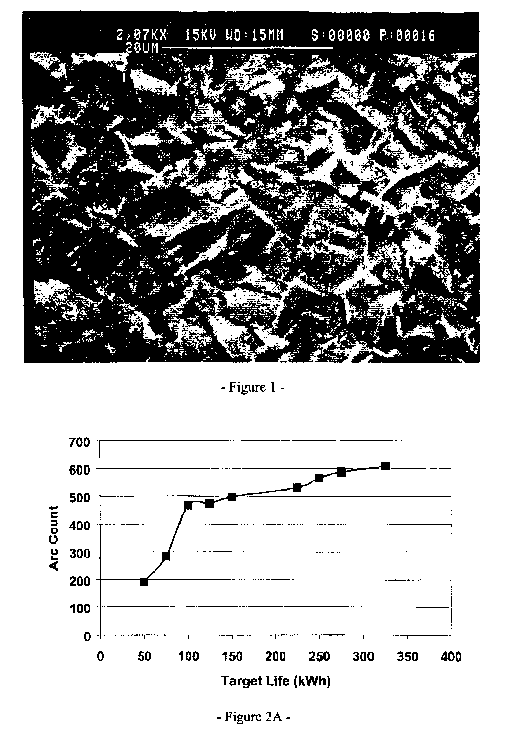
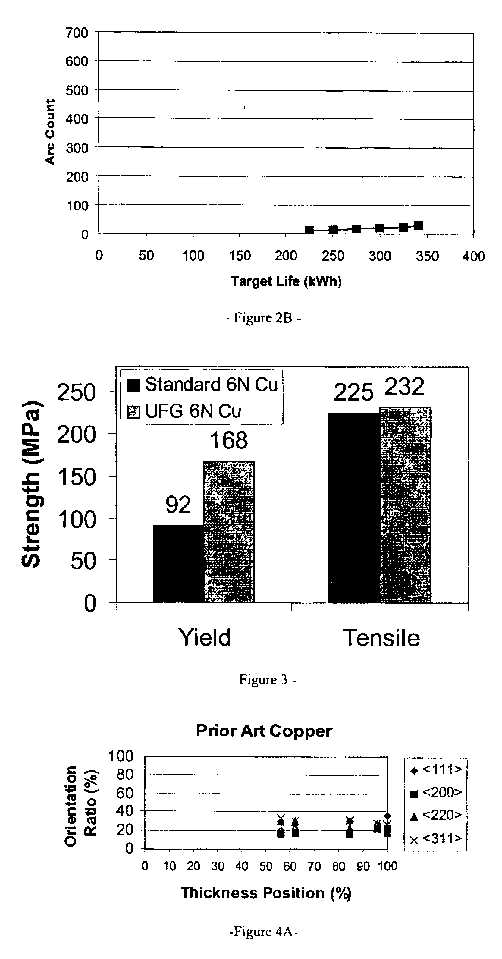
[0039]A 99.9999% pure Cu billet with a 7.0″ (17.8 cm) diameter was cut to a length of 6.45″ (16.38 cm) and subjected to cryogenic deformation processing as described in Example 1. The billet slice was cooled in liquid nitrogen to approximately 77K and cryogenically upset pressed in 4 steps (re-cooling between each step) to a final height of 4.5″ (11.43 cm). The workpiece was then cryogenic rolled down to a final thickness of 1.0 in (2.54 cm). Rolling passes took 0.10 in (0.25 cm) linear reduction per pass, and re-cooling in liquid nitrogen was conducted after every two passes. Following cryogenic deformation, the workpiece was annealed at 250° C. for 2 hours to develop an ultrafine grained structure. The grain size of the target blank of the present example was measured to be 3.6 μm and fully recrystallized. Tensile bars were machined from the target blank and pulled according to ASTM E-8 to gather stress-strain curves. Data from the tensile tests of the material from the present ex...


PUM

PropertyMeasurementUnit
Grain sizeaaaaaaaaaa
Lengthaaaaaaaaaa
Fractionaaaaaaaaaa

Abstract

The sputter target has a composition selected from the group consisting of high-purity copper and copper-base alloys. The sputter target's grain structure is at least about 99 percent recrystallized; and the sputter target's face has a grain orientation ratio of at least about 10 percent each of (111), (200), (220) and (311). In addition, the sputter target has a grain size of less than about 10 μm for improving sputter uniformity and reducing sputter target arcing.

Description

BACKGROUND OF THE INVENTION[0001]Recently, researchers have focused on the refinement of sputter target microstructures based on optimizing cold-working and recrystallizing heat treatments (annealing). Unfortunately, these techniques have experienced limited success for refining high-purity copper and copper alloy microstructures. Despite the relative ease of refining copper and copper alloys' microstructure, manufacturers are reliant upon conventional working and annealing to produce acceptable results. Most commercial manufacturers of copper sputter targets tend to produce sputter targets having a grain size between about 25 and 100 μm.[0002]Koenigsmann et al. in U.S. Pat. Pub. No. 2001 / 0023726 disclose the advantage of limiting a sputter target's grain size and controlling crystallographic texture orientation ratios to improve sputter uniformity. Koenigsmann's process relies upon a combination of warm working, cold working and annealing to produce high-purity copper sputter targe...

Claims


Application Information

Patent Timeline
IPC IPC(8): C22F1/08C23C14/34C22F1/00
CPCC23C14/3414C22F1/08C23C14/34
Inventor PERRY, ANDREW C.GILMAN, PAUL S.
Owner PRAXAIR ST TECH INC
Why Eureka
Try Eureka