
Anti-vibrational holding device for an electric motor

Inactive Publication Date: 2005-05-24
ROBERT BOSCH GMBH
View PDF10 Cites 54 Cited by
  • Summary
  • Abstract
  • Description
  • Claims
  • Application Information

AI Technical Summary

Benefits of technology

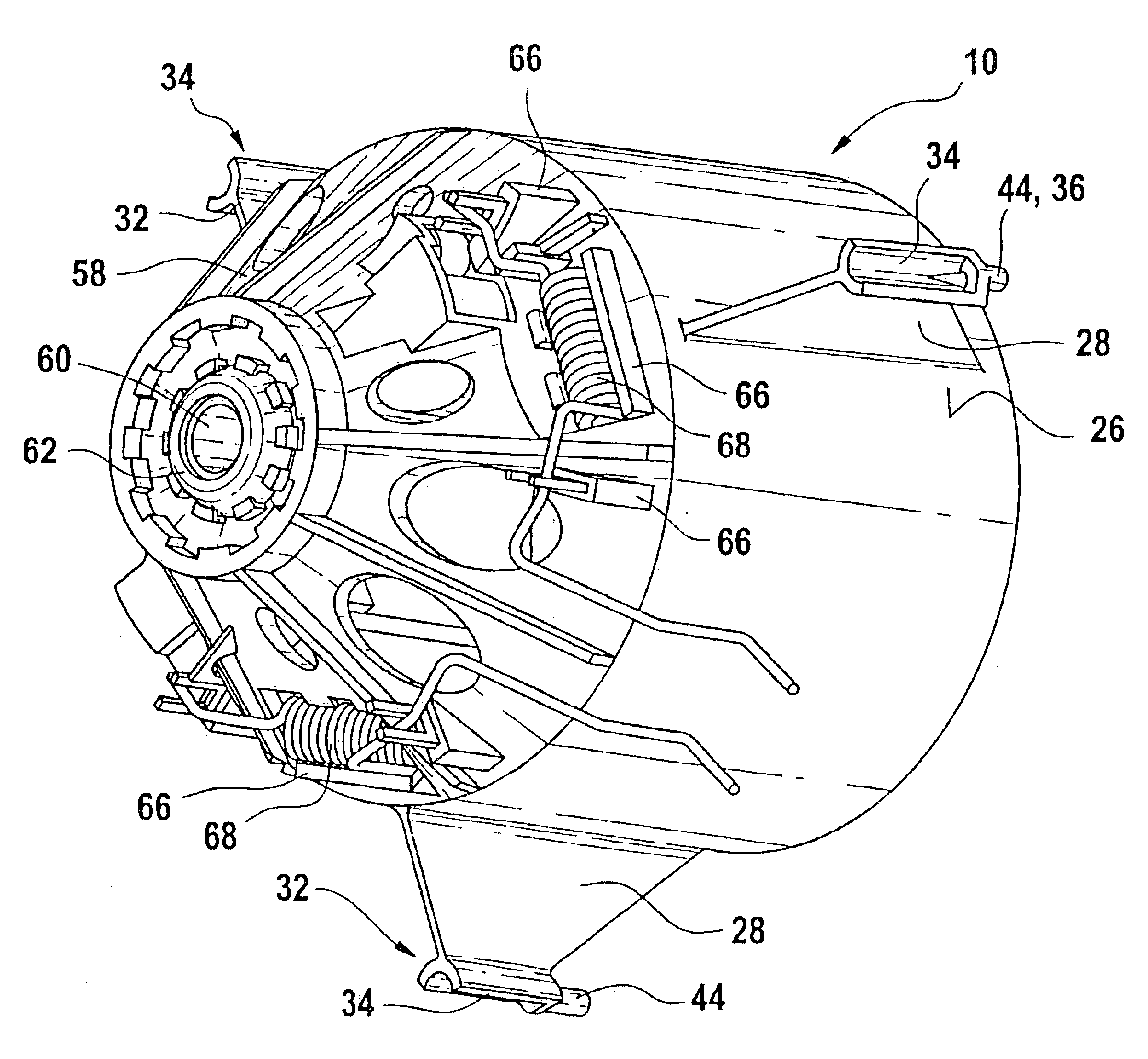
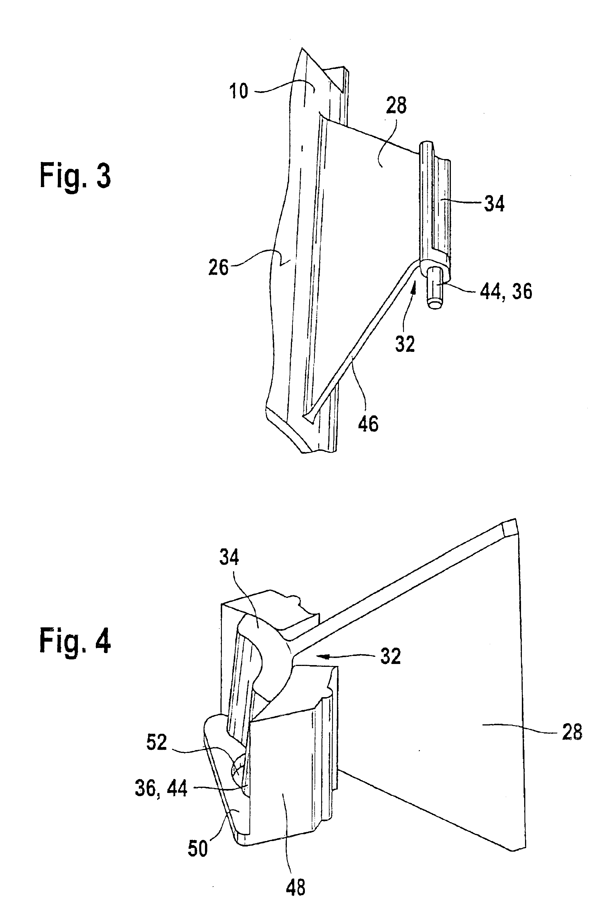
[0012]In their function, the plastic spokes of the invention represent a mechanical filter, which decouples the irritating torque pulses of the motor from the heating and air conditioning blower system, so that less vibration is transmitted to the system, and the noise level is reduced. This design has the advantage that the plastic spokes act as spring elements, without having to use rubber or rubber elements to damp the incident vibration.
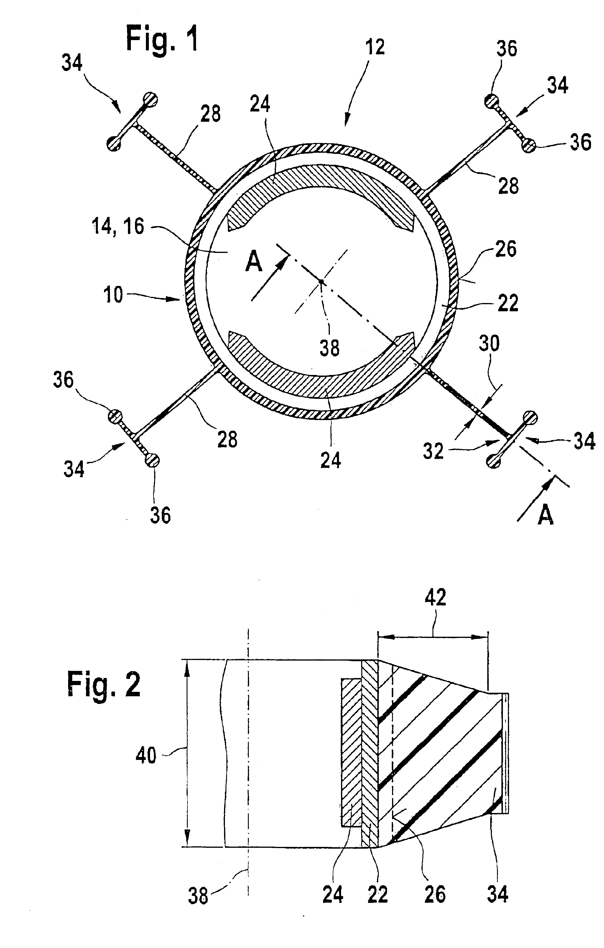
[0025]To further increase the connection strength, in an advantageous embodiment of the apparatus of the invention the recesses provided in the second housing part, which receive the plastic spokes of the first housing part, can taper conically in the axial direction, that is, in the direction of the motor shaft, specifically in such a way that the width of these recesses decreases in the direction of increasing distance from the first housing part. In this way it is attained that the plastic spokes, on their side toward the second housing part, can be clamped into the recesses of the second housing part. This assures a larger bearing area between the two housing parts and thus increases the mechanical stability of the apparatus of the invention.

Problems solved by technology

These elastic damping elements, which in a preferred embodiment of the apparatus of DE 43 34 124 A1 are suitably shaped rubber elements, represent increased expense for assembly and material, which unnecessarily increases the costs for such an apparatus.
In particular, rubber elements and rubber damping elements represent a problem for the assembly lines in industrial production, since they can be integrated into the corresponding apparatuses only by means of time-consuming manipulating processes.
Because of the three-point suspension in a single plane of the electric motor in U.S. Pat. No. 4,063,060 and the low spring constant of the retaining arms in the direction of torsion, this motor executes relatively major oscillating and tilting motions, which in the elastic elements, especially the buffers, engender shear forces that rapidly cause material fatigue and damage.
The service life of this known retaining device is therefore severely limited and is inadequate for use in motor vehicles, in which the elastic elements must also absorb vibration that is caused by external impacts from the roadway on the electric motor.

Method used


Image

  • Anti-vibrational holding device for an electric motor
  • Anti-vibrational holding device for an electric motor
  • Anti-vibrational holding device for an electric motor

Examples


Embodiment Construction

[0039]In FIG. 1, a first housing part 10 of the apparatus 12 of the invention is shown schematically. The housing part 10 in the exemplary embodiment of FIG. 1 is approximately cylindrical in shape, and on each of its axial ends it has a respective opening 14 and 16, through which a shaft 18 of an electric motor 20 can be guided out of the housing of the apparatus. The openings 14 and 16 can be closed by suitable caps, which can also comprise a different material from that of the first housing part 10. For instance, these caps can receive a brush holder part that belongs to the motor, or a bearing for the electric motor shaft, or other motor components.

[0040]A pole ring 22 and two segments of a permanent magnet 24 of the electric motor 20 of the apparatus 12 are inserted into the first housing part 10. In addition to the two-segment permanent magnet 24 shown here, it is understood that multi-pole magnets can also be used in the apparatus 12 of the invention.

[0041]On the outer circum...


PUM


Abstract

The invention relates to an apparatus for vibration-insulated mounting of an electric motor (20), in particular a blower motor, having a first housing part (10), which encloses at least one pole ring (22) and magnets (24) of the electric motor (20) and has at least one opening (14, 16), through which the shaft (18) of the motor (20) reaches, and having a second housing part (54), which is embodied as a motor flange for securing the electric motor (20) to a carrier element, for instance a motor vehicle heating and / or air conditioning system, and at least partly embraces the first housing part (10) in the axial direction of the motor shaft (18).It is proposed that on the outer circumference (26) of the first housing part (10), a plurality of radially extending, relatively flat plastic spokes (28) are provided, which engage associated, radially and axially extending recesses (57) of the second housing part (54), and which in the region of their radially outer end (32) have connecting means (36) for securing them to the second housing part (54).

Description

BACKGROUND OF THE INVENTION[0001]The invention is based on an apparatus for vibration-insulated mounting of an electric motor, in particular a blower motor.[0002]Blower motors for heating and air conditioning blower systems that are used in vehicles, for instance, are as a rule decoupled in terms of vibration from the vehicle, in order to reduce the transmission of structure-borne sound from the motor or blower unit to the vehicle body and hence the passenger compartment of the vehicle.[0003]Current methods of securing such motors comprise inserting the complete motor into a plastic housing or metal housing, on which a flange is provided for connection to the air conditioning system. Normally, rubber in the form of suitably shaped rubber elements is placed between the motor and the motor housing or into the flange, in order to damp sources of vibration of the air conditioning system or the vehicle body and to suppress noise that would be irritating to the driver or his passengers in...

Claims


Application Information

Patent Timeline
IPC IPC(8): F16F15/04F04D29/66H02K5/08H02K5/24H02K5/26H02K5/00F16F15/08
CPCF04D29/668F16F15/04H02K5/26H02K5/24H02K5/08
Inventor WHITE, ROBERT
Owner ROBERT BOSCH GMBH
Learn More