Method for controlling wire balls in electronic bonding

a technology of electronic bonding and wire ball, which is applied in the direction of manufacturing tools, non-electric welding apparatus, printed circuit manufacturing, etc., can solve the problems of not meeting the cost effectiveness goals of semiconductor mass production driven by flexibility and low cost requirements, and the method is too expensive for today's high number of bonds required per second in semiconductor mass production, etc., to achieve the effect of avoiding wire necking and minimizing the time spent for creating the free air ball

Inactive Publication Date: 2005-05-31
TEXAS INSTR INC
View PDF20 Cites 17 Cited by
  • Summary
  • Abstract
  • Description
  • Claims
  • Application Information

AI Technical Summary

Benefits of technology

[0018]In the second embodiment of the invention, a pulse current of a pre-determined height is applied for a specific period of time. Directly afterwards, a second pulse of much lesser height and time is applied, followed by a third pulse of intermediate height y...

Problems solved by technology

This method, together with the requirement of a gas shroud, is too expensive for today's high number of bonds required per second in semiconductor mass production.
Similarly, related techniques, which are based on protective gas shrouds and/or time-consuming arc energy delivery, do not meet the goals for cost effectiveness in semiconductor mass production driven by flexibility and low cost requirements.
Other techniques propose to control specific features in wire ball bonding, such as ball size or shape, but do...

Method used


Image

  • Method for controlling wire balls in electronic bonding
  • Method for controlling wire balls in electronic bonding
  • Method for controlling wire balls in electronic bonding

Examples


first embodiment

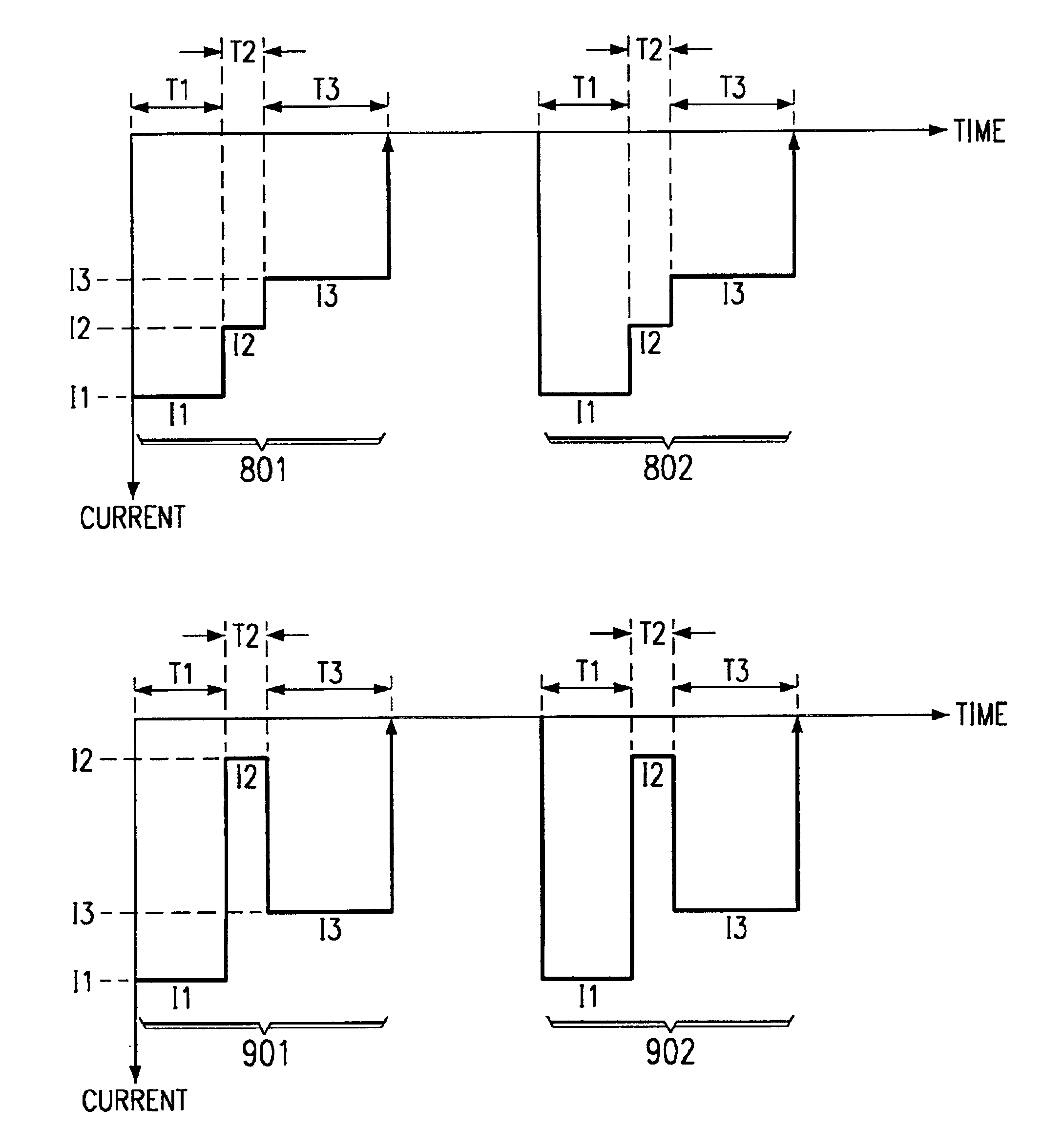
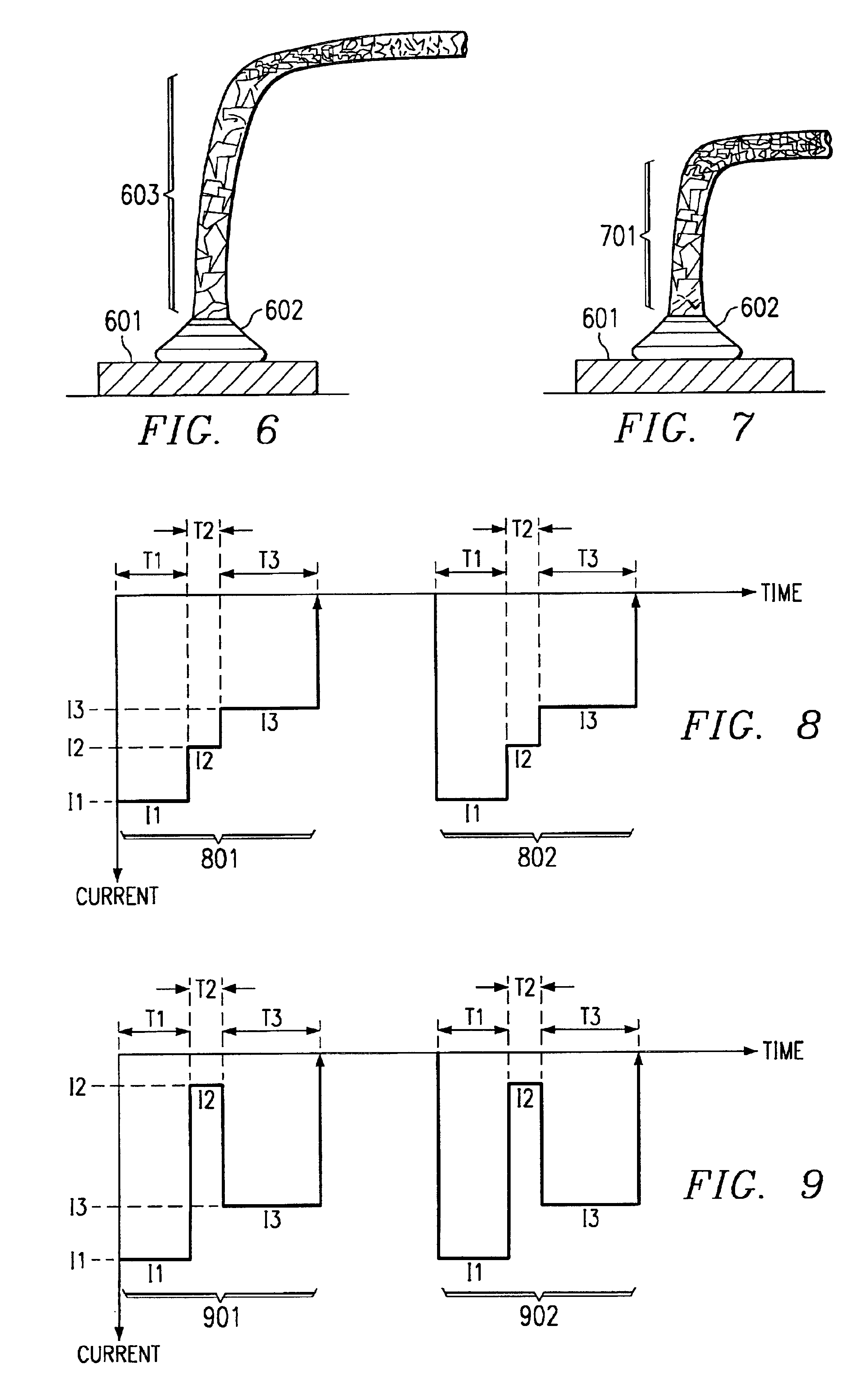
[0039]The sequence of EFO current pulses of the present invention is illustrated in FIG. 8. Plotted in FIG. 8 is EFO current versus time. One train of pulses 801 consists of a first pulse of pre-determined height I1 applied for a specific period of time T1. Directly afterwards, a second pulse of lesser height I2 and time T2 is applied, followed by a third pulse of still lesser height I3 yet longer duration T3. This sequence of pulses is designed to create small, substantially spherical free air balls and to minimize the heat-affected zone, especially for gold wires. Examples of parameter values for gold wire diameter, EFO current height and time length, with designations as in FIG. 8, are listed in the following Table 1.

[0040]

TABLE 1Gold wire diameter 23-25 μmBall diameter 70-80 μmBall diameter 65-75 μmHeight (mA)Length (ms)Height (mA)Length (ms)First pulse I1 = 10T1 = 2I1 = 8L1 = 2Second pulseI2 = 7T2 = 1I2 = 5T2 = 1Third pulseI3 = 5T3 = 5I3 = 4T3 = 5

[0041]It is an option to omit t...

second embodiment

[0044]The sequence of EFO current pulses of the present invention is illustrated in FIG. 9. Plotted in FIG. 9 is EFO current versus time. One train of pulses 901 consists of a first pulse of pre-determined height I1 applied for a specific period of time T1. Directly afterwards, a second pulse of much lesser but not zero height I2 and time T2 (to keep the arc burning) is applied, followed by a third pulse of intermediate height I3 yet longer duration T3. In the period T2, the EFO arc is still maintained, while overheating of the newly formed free air ball is avoided and the ball is still kept hot for the next pulse I3. This sequence of pulses is designed to provide the energy needed for creating small, substantially spherical free air balls and avoiding wire necking. Examples of parameter values for gold wire diameter, EFO current height and time length, with designations as in FIG. 9, are listed in the following Table 2.

[0045]

TABLE 2Gold wire diameter (μm) 23-25Ball diameter 70-80 μ...


PUM

PropertyMeasurementUnit
Timeaaaaaaaaaa
Currentaaaaaaaaaa
Currentaaaaaaaaaa

Abstract

A method for forming a substantially spherical free air ball on a fine non-oxidizable wire in a computerized bonder, which has a computerized flame-off (EFO) apparatus operable to generate pulses of different heights and widths. A train of EFO current pulses is applied between electrode and wire; examples are shown in FIGS. 8 and 9. The pulse heights are controlled to melt a predetermined volume of wire while minimizing the heat-affected zone of the wire as well as the wire necking, thus creating free air balls of small diameters and high ball/wire strength. The pulse widths are controlled to create a substantially spherical ball shape. The pulse train of various heights and widths is minimized in order to minimize the time needed for one bond and to maximize the number of bonds provided per second.

Description

[0001]This application claims the benefit of Provisional Application No. 60 / 235,682, filed Sep. 27, 2000.FIELD OF THE INVENTION[0002]The present invention is related in general to the field of semiconductor devices and electronic systems and more specifically to the controlled operation of computerized bonding machines used in the assembly of integrated circuit chips.DESCRIPTION OF THE RELATED ART[0003]In integrated circuit (IC) assembly, an IC chip is first mechanically attached to the chip mount pad of a pre-fabricated leadframe. Thereafter, the chip bond pads are electrically connected to the leadframe segments by a plurality of electrical conductors. Typically, the IC bond pads (usually made of aluminum, copper, gold, or alloys thereof) are positioned around the chip perimeter and vary in size from 45×45 μm to 150×150 μm. The technology trend is strongly aiming at ever smaller pad sizes. Furthermore, the pitch of the smallest pads is shrinking from 60 μm to 50 μm and less, while...

Claims


Application Information

Patent Timeline
IPC IPC(8): B23K20/00H01L21/607H01L21/02
CPCB23K20/007H01L24/48H01L24/78H01L24/85H01L24/45H01L2224/05624H01L2224/05647H01L2224/45015H01L2224/45144H01L2224/45147H01L2224/48091H01L2224/4845H01L2224/48463H01L2224/4851H01L2224/48511H01L2224/48624H01L2224/48647H01L2224/48847H01L2224/78268H01L2224/78301H01L2224/78901H01L2224/85045H01L2224/85205H01L2924/01004H01L2924/01006H01L2924/01012H01L2924/01013H01L2924/01014H01L2924/0102H01L2924/01028H01L2924/01029H01L2924/01046H01L2924/01047H01L2924/01075H01L2924/01079H01L2924/01327H01L2924/14H01L2924/20751H01L2924/20752H01L2924/20753H01L2924/20754H01L2924/20755H01L2924/20756H01L2924/20757H01L2924/01033H01L2224/45124H01L2224/48699Y10T29/49144Y10T29/49149H01L2924/01026H01L2924/00014H01L2924/00011H01L2924/00H01L2224/45139H01L2224/48824H01L2224/48724H01L2224/48747H01L2224/45014H01L2924/00015H01L2924/2075H01L2924/206
Inventor TREJO, LUIS
Owner TEXAS INSTR INC
Why Eureka
Try Eureka