
IC card

a technology of ic cards and insulating pads, applied in the field of ic cards, can solve the problems of limited recording capacity, high cost of ic cards, and well protected, and achieve the effects of minimizing recording unevenness, minimizing the generation of irregularities, and obtaining durability

Inactive Publication Date: 2005-05-31
KONICA CORP
View PDF1 Cites 29 Cited by
  • Summary
  • Abstract
  • Description
  • Claims
  • Application Information

AI Technical Summary

Benefits of technology

"The present invention provides an IC card that can be surface smoothened and has minimal recording unevenness while being durable. Additionally, the invention provides an IC card that can be easily identified and targeted for malicious acts. The invention also enhances the durability of the IC card by making the position of the IC chip section difficult to identify. The invention is achieved by varying the antenna to a specified shape and adding an IC chip hiding part to thwart malicious acts. The resulting IC card exhibits excellent smoothness and durability of the card surface."

Problems solved by technology

However, problems have occurred in which since in magnetic cards, it is possible to relatively easily rewrite data, data are not effectively secured from falsification, data are not well protected due to external magnetic effects, and further, the recording capacity is limited.
As a result, such ID cards have increasingly been employed for the past several years, but have not yet employed as a standard.
As a result, the resultant IC cards become quite expensive.
Due to that, problems occur in which free presentation is limited in such a manner that it is required to carry out a layout on the surface of cards so that the concave portion of the image receptive layer is not printed.
Further, even though the surface is smooth, it has been difficult to obtained desired printing characteristics due to the partial difference in heat conductivity.
Specifically, from the viewpoint of image reproduction, major problems have occurred in which information comprised of image information such as a portrait image, having gradation characteristics, is printed employing a thermal transfer system.
Further, problems have occurred in which the visual appearance is degraded due to the identification of the position of IC chips when the IC card is exposed to light.
However, the resultant effect has not been sufficient.
Problems have occurred in which the IC chip portion identified as above is destroyed to eliminate personal information so that card issuing industries are troubled.
Such IC cards cause problems in poor visual appearance as well as poor resistance against malicious acts.

Method used


Image

  • IC card
  • IC card
  • IC card

Examples


synthesis example 1

Synthesis Example 1 of Resin Added to IC Card Surface Protective Layer

[0284]Placed in a three-necked flask were 73 parts of methyl methacrylate, 15 parts of styrene, 12 parts of methacrylic acid, 500 parts of ethanol, and 3 parts of α,α′-azobisisobutylnitrile, and the resultant mixture underwent reaction in an oil bath at 80° C. under a flow of nitrogen for 6 hours. Thereafter, 3 parts of triethylammonium chloride and 1.0 part of glycidyl methacrylate were added and the resultant mixture underwent reaction for 3 hours, whereby target Synthesis Binder 1, comprised of an acryl based copolymer, was prepared.

[0285]A coating composition, prepared by employing the formula described below, was applied onto one surface of polyethylene terephthalate (S-25), manufactured by Daifoil Hoechst Co., Ltd. employing wire bar coating, and subsequently dried, whereby Transfer Foils 1 through 3 were formed.

[0286]

(Preparation of Transparent Resin Transfer Foil 1)(Releasing Layer) Layer thickness of 0.5 ...


PUM


Abstract

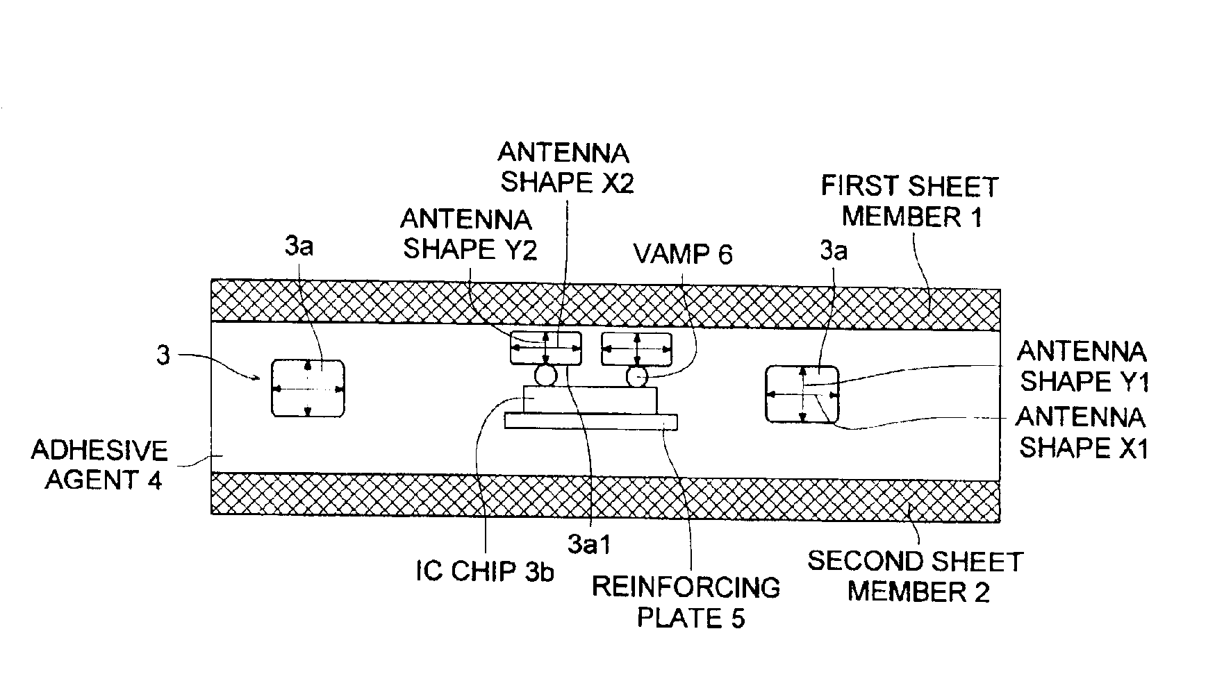
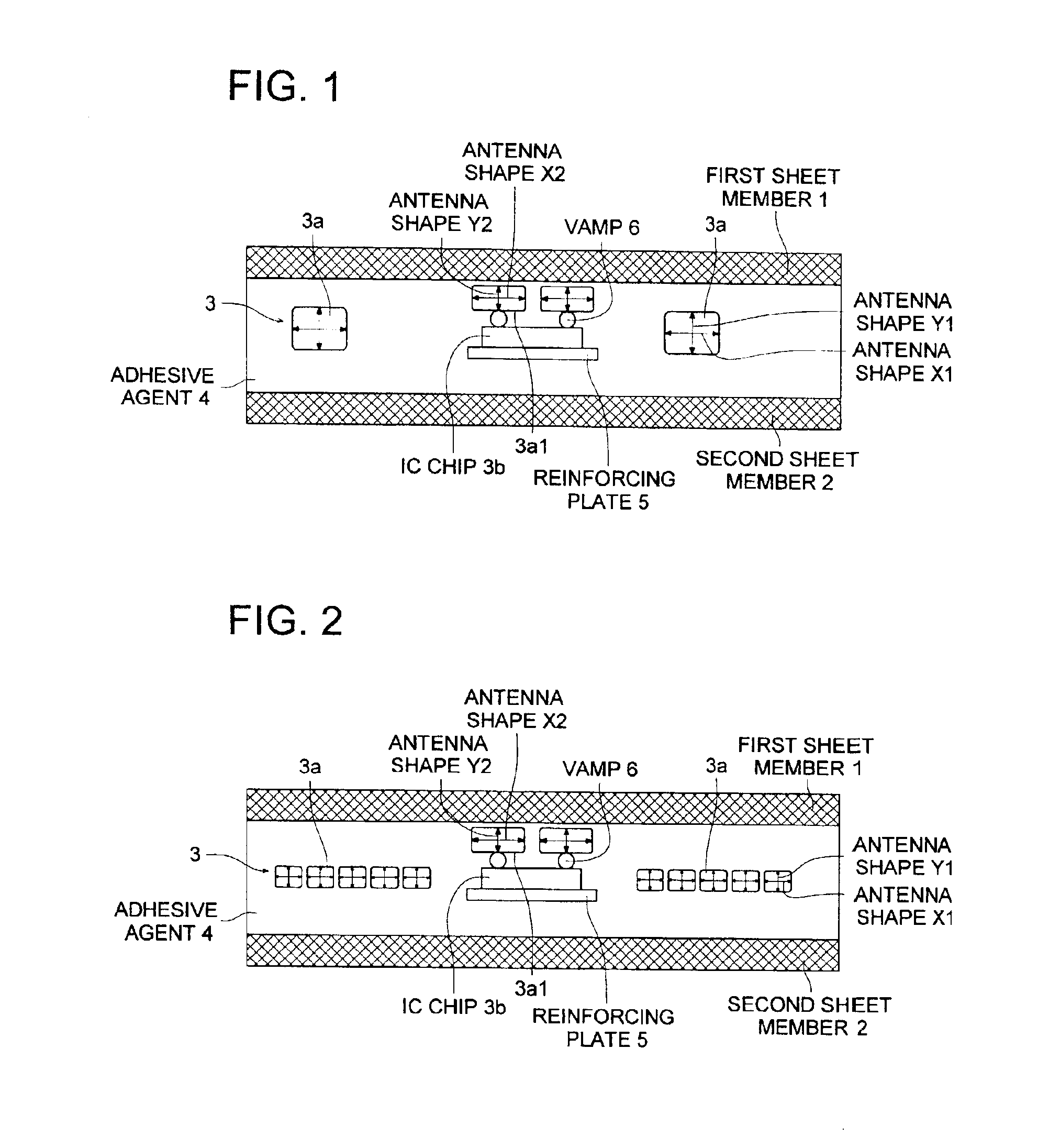
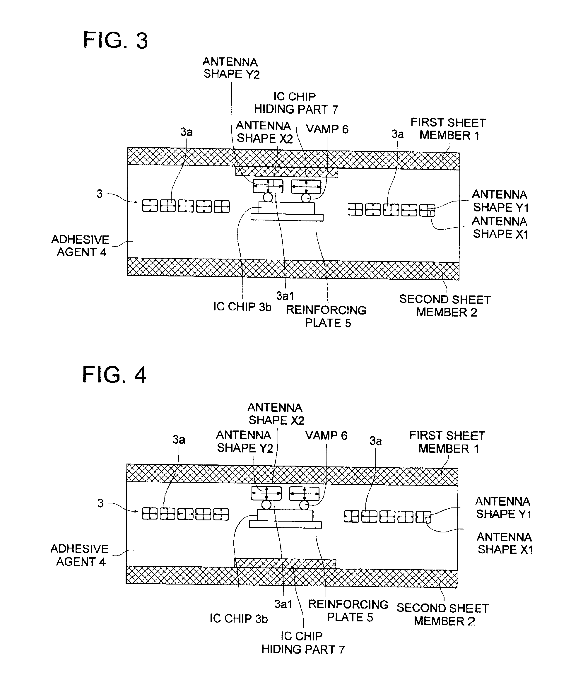
An IC card comprising: a first sheet member; a second sheet member; and a core layer fixed therein an electronic part by an adhesive agent and provided between the first sheet member and the second sheet member. The electronic part comprises an antenna coil formed by an antenna wire and an IC module comprising an IC chip. The antenna wire has a structure represented by following General Formula 1,Antenna Shape X1 ≧Antenna Shape Y1×1.2wherein Antenna Shape X1 represents the cross sectional width of the antenna wire being parallel to the surface of the IC card; Antenna Shape Y1 represents the cross sectional width of the antenna wire being perpendicular to the surface of the IC card.

Description

FIELD OF THE INVENTION[0001]The present invention relates to an IC card which comprises in its interior a non-contact type IC module which stores personal information which requires security against forgery as well as falsification.BACKGROUND OF THE INVENTION[0002]Heretofore, magnetic cards, which record data employing a magnetic recording system, have widely been employed as, for example, identification cards (ID cards), credit cards, and the like. However, problems have occurred in which since in magnetic cards, it is possible to relatively easily rewrite data, data are not effectively secured from falsification, data are not well protected due to external magnetic effects, and further, the recording capacity is limited.[0003]In some ID cards, for example, the surface comprises portrait (face image) as well as text information and the back surface comprises a writing layer capable of being manually written upon. It is possible to easily prepare such ID cards at low cost due to the...

Claims


Application Information

Patent Timeline
Patent Type & Authority Patents(United States)
IPC IPC(8): G06K19/077B42D15/10G06K19/07H01L21/56H01L23/00
CPCG06K19/07749G06K19/0775H01L2224/16H01L2924/0102H01L2924/01025H01L2224/16225H01L2924/3025H01L2924/01019H01L2924/12041H01L2224/16227H01L2924/01079H01L2924/12044H01L2924/00G06K19/077
Inventor HATTORI, RYOJI
Owner KONICA CORP
Learn More