Microstructured optical fiber

a microstructured, optical fiber technology, applied in the direction of glass optical fibre, clad optical fibre, instruments, etc., can solve the problem that the sub medium is not necessarily able to constitute an optical fiber by itsel

Inactive Publication Date: 2005-05-31
SUMITOMO ELECTRIC IND LTD
View PDF12 Cites 85 Cited by
  • Summary
  • Abstract
  • Description
  • Claims
  • Application Information

AI Technical Summary

Benefits of technology

[0005]The present invention fulfills the above described needs, at least in part by providing a fiber having optical characteristics in which the bending loss of the fundamental mode is low, the bending loss of the first higher-order mode is high, and the mode-field diameter is suited for low-loss optical coupling and low-loss guiding. Terminology used herein in describing the invention is characterized as follows.

Problems solved by technology

On the other hand, a sub medium is not necessarily able to constitute an optical fiber by itself.

Method used


Image

  • Microstructured optical fiber
  • Microstructured optical fiber
  • Microstructured optical fiber

Examples


first embodiment

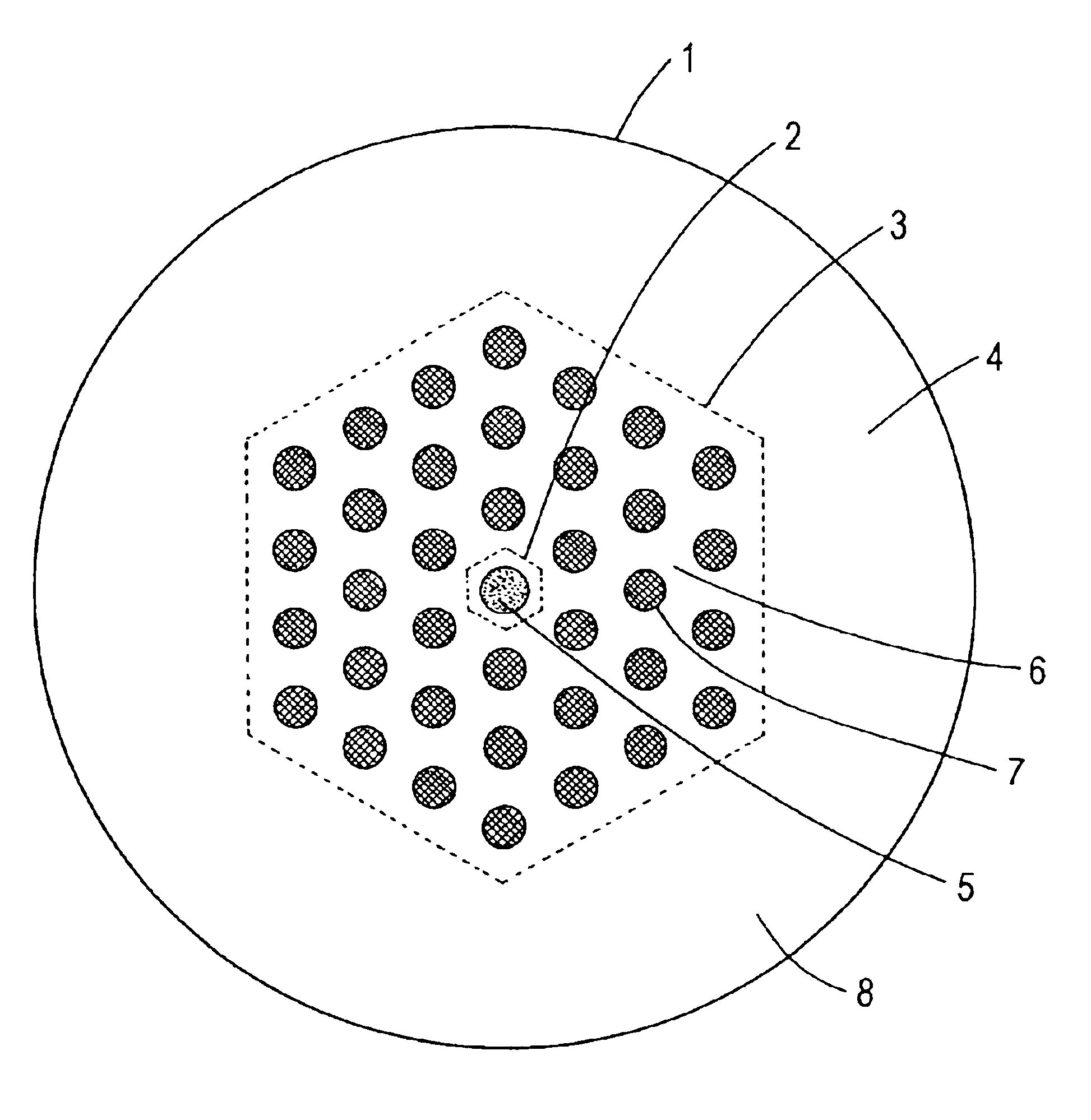
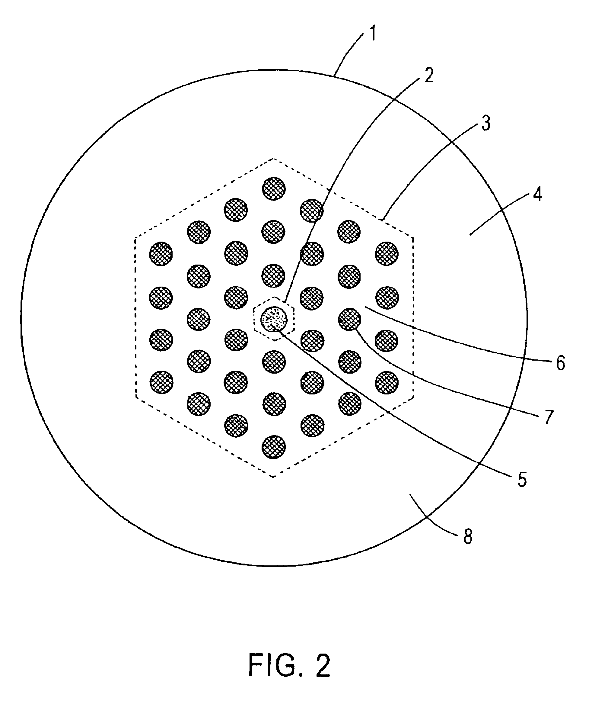
[0035]In the microstructured optical fiber of this first embodiment, the shapes of the region of the first main medium and the air holes are circles in the cross section perpendicular to the fiber axis. The air holes are arranged on lattice points of a hexagonal lattice of a constant pitch L. The number of the air holes is 36, and they occupy three layers of the hexagonal lattice. The refractive index in the region of the first main medium is substantially spatially uniform. It is also possible to dope silica glass of the first to the third main medium with germanium, fluorine, chlorine, boron, aluminum, and titanium and to form a refractive index profile. Also, while the index profile in the core region is known as step-index profile, other profiles such as one known as W-shaped profile are also possible. In addition, the arrangement of the air holes need not be a hexagonal lattice. Instead, it is possible to arrange the sub medium regions on a plurality of co-centered circumferenc...

embodiment 1

[0046]It also should be noted that the fibers A1-A3 of embodiment 1 are more suited than the fibers B1-B3 while the difference between Ak and Bk (k=1, . . . , 3) is only in the number of the holes. Such influence of the number of the holes on the performance as fibers for wiring applications has not been found out in previously known fibers.

[0047]As in the first embodiment, because of low bending loss of the fundamental mode, those optical fibers can operate under small-diameter bends. Because of high bending loss of the first higher-order mode, the multimode noise due to interference between the fundamental and higher-order modes is low. Moreover, since the mode-field diameter is between 8.0 μm and 50 λ either with or without the sub medium regions, it is possible to realize optical coupling with external optical systems with low optical loss and low cost. Also, the power fraction located in the holes is lower than 10−4, so that the transmission loss due to absorption or scattering...

second embodiment

[0059]The inventors have fabricated and evaluated several optical fibers of the present invention. FIG. 17 shows the images of the cross sections of the fabricated optical fibers (a) to (d) taken by scanning electron microscope. Each of the four fibers has a similar structure to that of the second embodiment shown in FIG. 4, so that each fiber has a core, a first inner cladding, a second inner cladding, and an outer cladding. The core has a region made of germanium-doped silica surrounded by pure silica, wherein the relative refractive index difference Δ of the doped region to pure silica is about 0.33% and the diameter of the region is about 8.5 μm. The inner cladding regions are made of pure silica glass and air holes embedded in the glass. The outer cladding is made of pure silica. The difference between the four fibers is in the diameter of the holes.

[0060]Table 4 summarizes the optical properties and structure of the fabricated fibers. As shown in the table, the fabricated fibe...


PUM

PropertyMeasurementUnit
bending diameteraaaaaaaaaa
mode-field diameteraaaaaaaaaa
bending diameteraaaaaaaaaa

Abstract

An optical fiber suitable for use in a single fiber or multifiber optical connector or array is structured with a core region and a cladding region surrounding the core region, and exhibits a bending loss of a fundamental mode of the fiber at a wavelength λ is lower than 0.1 dB/m at a diameter of 15 mm, a mode-field diameter of the fundamental mode at an end of the fiber at the wavelength λ is between 8.0 μm and 50 λ, and a bending loss of a first higher-order mode at the wavelength λ is higher than 1 dB/m at a diameter of 30 mm. The fiber may be multistructured, wherein the cladding region comprises a main medium and a plurality of sub medium regions therein to form a spatially uniform average refractive index.

Description

FIELD OF THE INVENTION[0001]The present invention relates to fiber optic waveguides, more particularly to arrangements of sub medium regions in microstructured optical fibers.BACKGROUND[0002]A conventional optical fiber is illustrated in FIG. 1. Shown in cross section, a first main medium 5c, having a predetermined refractive index, is surrounded by a second main medium 6c, having a refractive index lower than that of the first main medium. The core region 2c includes the first main medium, so that a lightwave localizes in the core and propagates over the fiber. The refractive index of the first main medium is typically spatially uniform, while other well-known profiles such as W-shaped profile are possible.[0003]The recent development of the microstructured optical fiber, in which a high index core region is surrounded by cladding having a mix of silica and air, offers new fiber properties by virtue of the large refractive-index contrast that exists between glass and air. A claddin...

Claims


Application Information

Patent Timeline
Patent Type & Authority Patents(United States)
IPC IPC(8): C03C13/04C03C13/00G02B6/00G02B6/36G02B6/12G02B6/02
CPCC03C13/04G02B6/02333G02B6/02338G02B6/02357G02B6/02361G02B6/02347G02B6/02395G02B6/262F16D65/128F16D2065/132F16D2065/1328
Inventor HASEGAWA, TAKEMISASAOKA, EISUKENISHIOKA, DAIZOUEDA, TOMOHIKOHOSOYA, TOSHIFUMI
Owner SUMITOMO ELECTRIC IND LTD
Why Eureka
Try Eureka