

Method and apparatus for improved optical elements for vertical PCB fiber optic modules
a technology of fiber optic modules and optical elements, applied in the field of light bending devices, can solve the problems of increasing the cost of fiber optic transceivers, affecting the performance of optical elements, and requiring additional components for using separate optical elements, so as to reduce the footprint of fiber optic modules, improve optical elements, and minimize manufacturing costs
- Summary
- Abstract
- Description
- Claims
- Application Information
AI Technical Summary
Benefits of technology
Problems solved by technology
Method used
Image

Examples
second embodiment
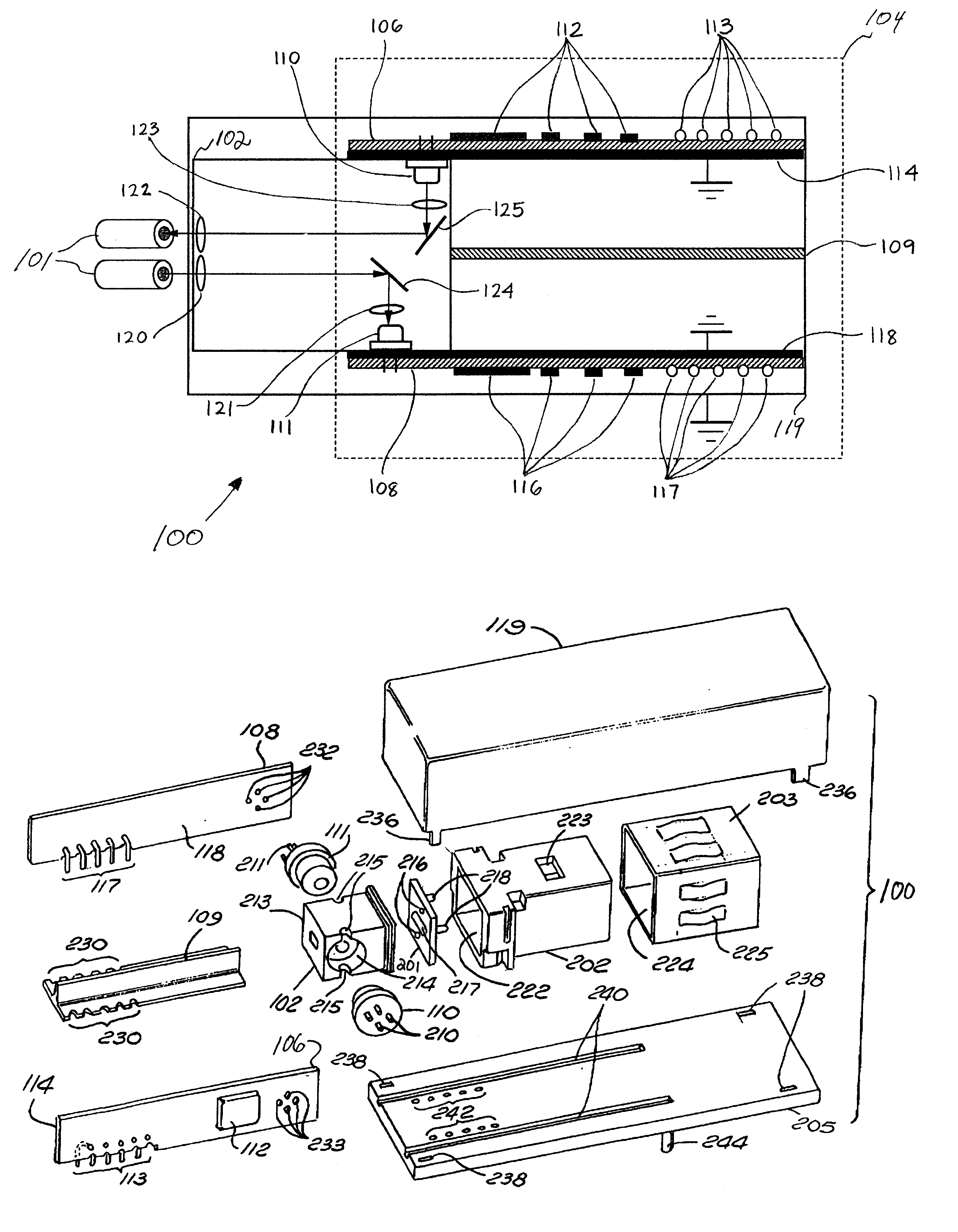
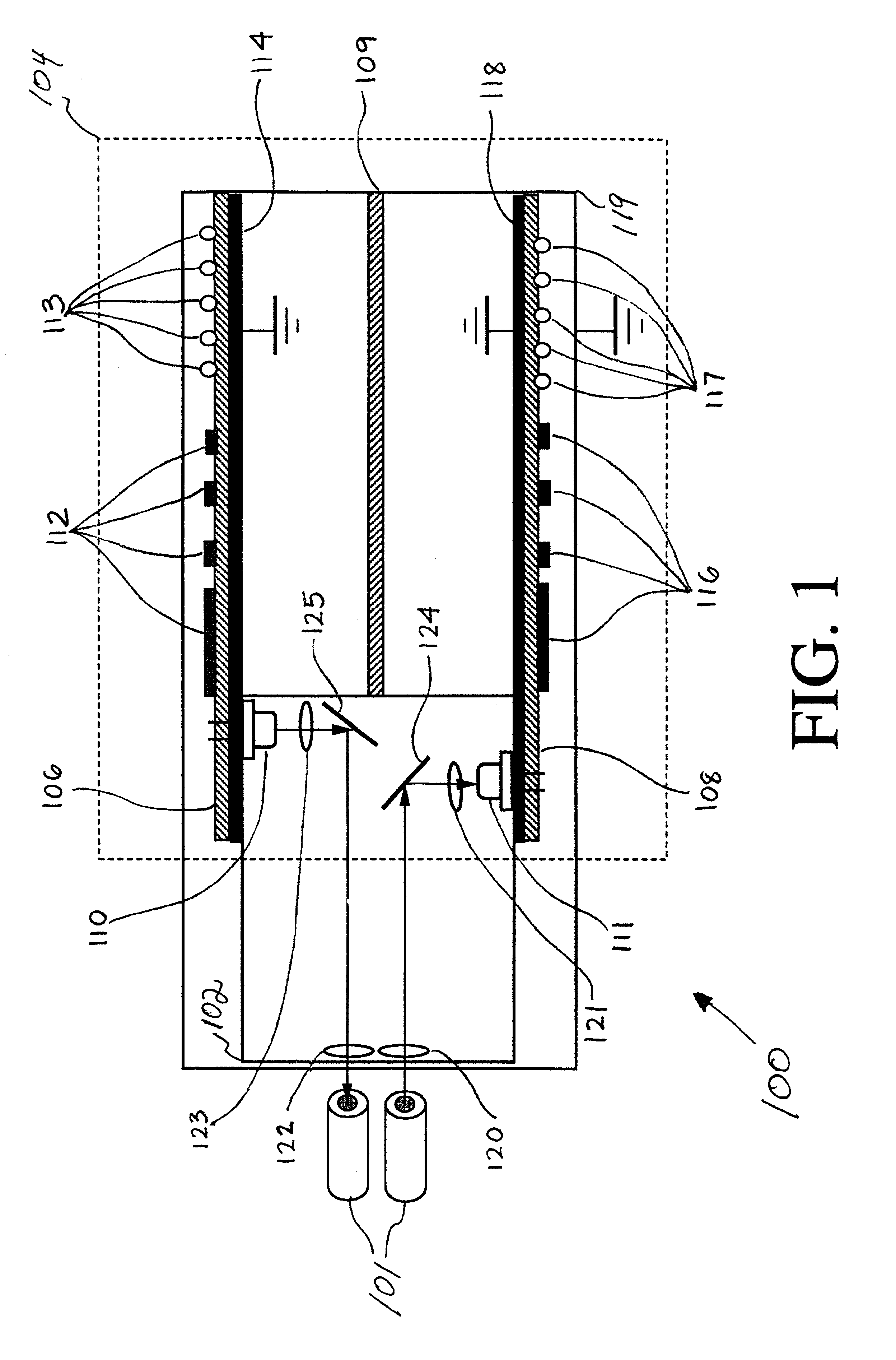
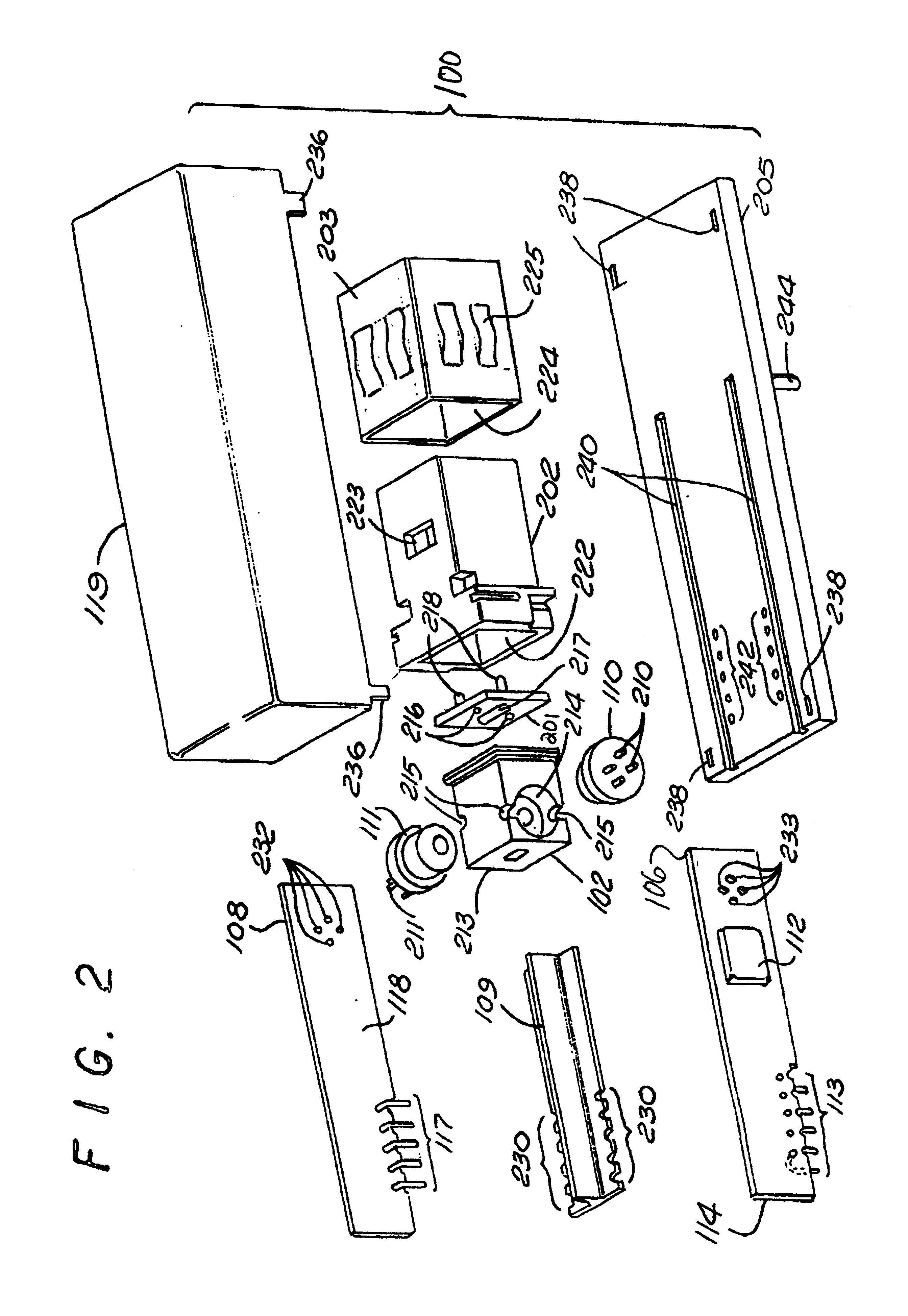
[0043]The present invention includes a method, apparatus and system for improved optical elements for vertical PCB fiber optic modules. Briefly, fiber optic transmitter and receiver electrical elements are implemented on two separate substantially parallel boards in a fiber optic transceiver modules. The parallel boards are mounted substantially perpendicular to the base of the fiber optic module and the system printed circuit board to which it attaches, to reduce the footprint of the fiber optic module. In one embodiment, bending light or photons through ninety degrees, the light transmitter (a packaged type of emitter) and a light receiver (a packaged type of photodetector) are each mounted substantially perpendicular to the transmit and receive boards respectively such that their active areas are nearly facing each other but offset. A single optical block implements lenses and reflecting surfaces to minimize manufacturing costs. The light receiver and light transmitter are mounte...
third embodiment
[0044]In the present invention, the light receiver and light transmitter are coupled to the receive board and transmit boards on an angle facing towards the optical fibers. The receiver and transmitter can be mounted directly across from each other without any offset in position because they do not face each other but are coupled at an angle and can avoid optical cross talk. A single optical block can provide the lenses and reflecting surfaces to minimize manufacturing costs. The reflecting surface for transmission may include a beam shaper to mix the spatial modes uniformly and to reduce beam alignment sensitivity for coupling the light into the fiber, such that passive alignment need only be used. The beam shaper furthermore improves the launching of light or photons into a multimode optical fiber to stimulate other modes such that differential mode delay effect and modal noise is reduced. The separate and substantially parallel receive and transmit boards are provided with ground...
fourth embodiment
[0045]In the present invention, the light receiver and light transmitter are coupled to the receive board and transmit boards on an angle facing away from the optical fibers. The receiver and transmitter can be mounted directly across from each other without any offset in position because they do not face each other but are coupled at an angle and can avoid optical cross talk. A single optical block can provide the lenses and reflecting surfaces to minimize manufacturing costs. The reflecting surface for the transmitter may include a beam shaper to uniformly mix the spatial modes and increase the beam size to decrease the alignment sensitivity of coupling light into the fiber, such that passive alignment need only be used. The beam shaper furthermore improves the launching of light or photons into a multimode optical fiber to stimulate other modes such that differential mode delay effect and modal noise are reduced. The separate and substantially parallel receive and transmit boards...
PUM
 Abstract
Description
Claims
Application Information