Fuselage pitot-static tube

a pitot-static tube and fuselage technology, which is applied in the direction of liquid/fluent solid measurement, golf clubs, instruments, etc., can solve the problems of increased aerodynamic, increased shock drag of such a pitot-static tube, and inability to apply pitot-static tube to determine the angle of attack, so as to reduce power loss, reduce the length of the pst, and increase the design weight

Inactive Publication Date: 2005-06-07
ZHUKOVSKY N E +2
View PDF8 Cites 12 Cited by
  • Summary
  • Abstract
  • Description
  • Claims
  • Application Information

AI Technical Summary

Benefits of technology

[0057]It is known that the formation of ice during flight in the atmosphere chiefly affects areas of flow deceleration or areas where a separation of flow is formed. Owing to the occurrence on them of streams with flow separation, sharp leading edges are frequently more subject to the formation of ice than are rounded-off ones. Since, by contrast with the lens-shaped profile, where even at small angles of attack a stream is formed with separation of flow from the leading edge, there is no separation of flow at small angles on a subsonic aerodynamic profile with a rounded-off nose, the strut of the proposed PST is less subject to the formation of ice than the strut of the PST prototype. Moreover, in the case of the strut of the PST prototype, because of the fact that it has a cross-section in the form of a lens-shaped profile, it is difficult or virtually impossible to arrange the electric heaters of the anti-icing system immediately next to the nose of the profile, since the volumes required for this are not present inside. Consequently, the electric heaters for suc

Problems solved by technology

However, this Pitot-static tube cannot be applied for determining the angle of attack, since it lacks orifices for sensing pressure with the aid of which the angle of attack can be measured.
In fact, as follows from the above-mentioned patent, this tube is not intended for these purposes.
This leads, in turn, in the case of high sub-sonic speeds (Mach numbers of M=0.8-0.9) to the earlier appearance of local pressure shocks and a marked increase in the shock drag of such a Pitot-static tube.
The given PST has the following disadvantages:a complicated design;increased overall dimensions of the axisymmetric body;increased aerodynamic drag in subsonic flight regimes;increased required power for the heater of the anti-icing system;increased design weight;i

Method used


Image

  • Fuselage pitot-static tube
  • Fuselage pitot-static tube
  • Fuselage pitot-static tube

Examples


Embodiment Construction

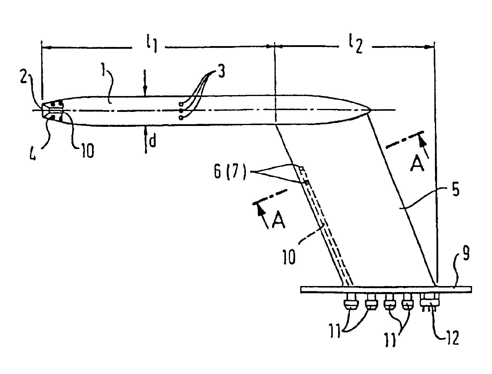
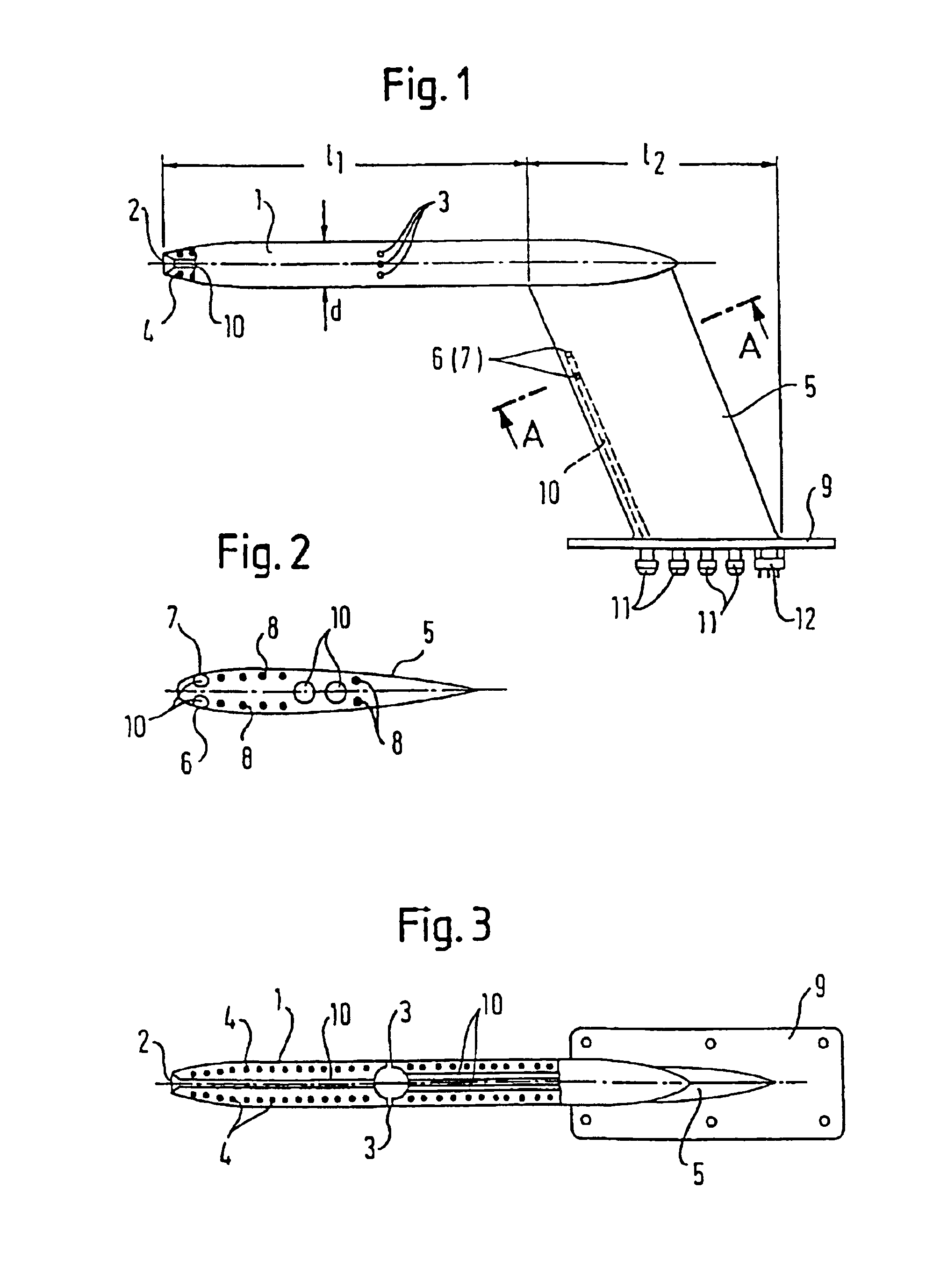
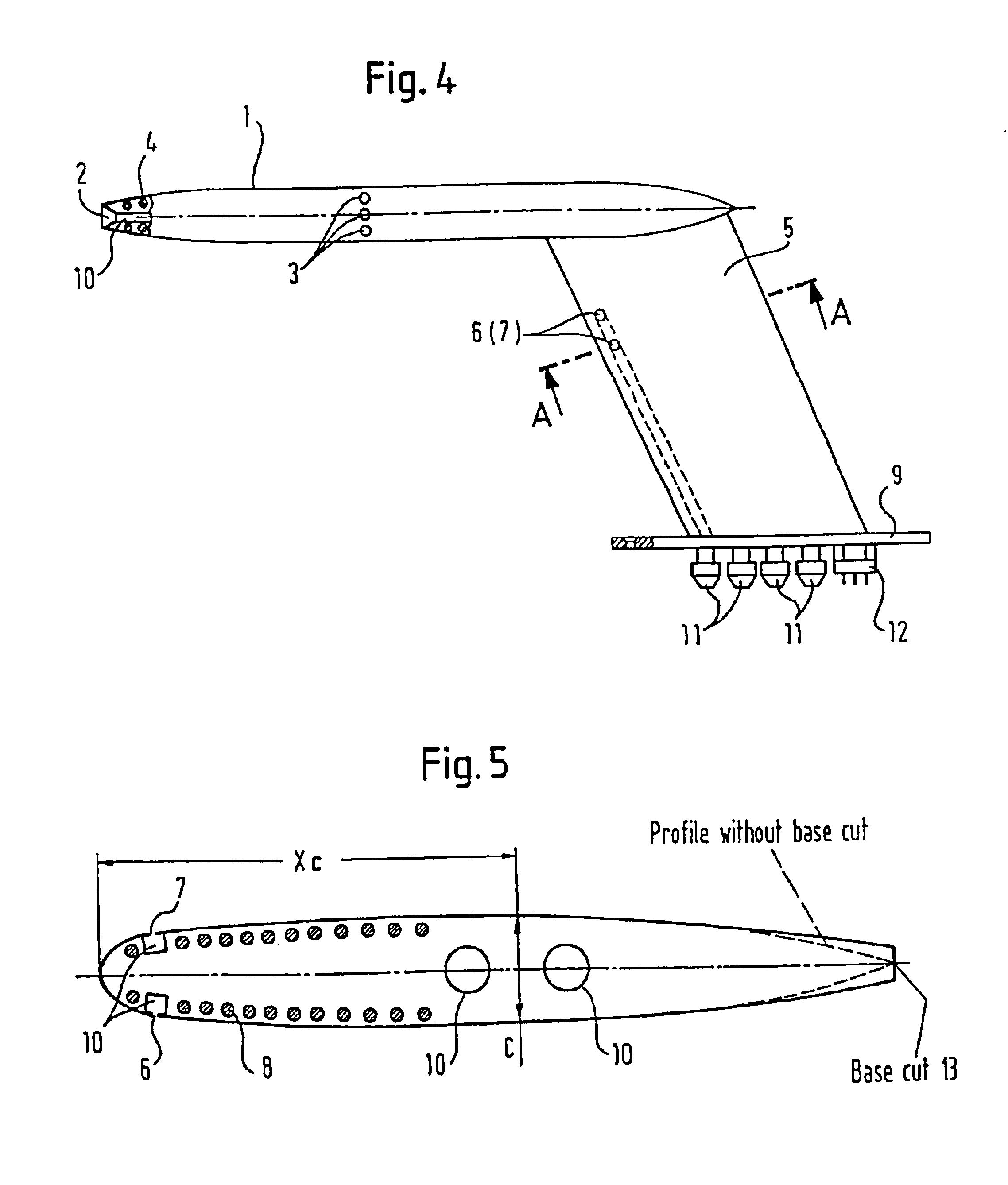
[0088]The fuselage Pitot-static tube (FIG. 1) comprises an axisymmetric body 1 in whose nose part an orifice 2 is arranged for determining total pressure; orifices 3 for sensing static pressure are arranged on the lateral surface. TEHs 4 of an anti-icing system are located inside the axisymmetric body 1. The axisymmetric body is mounted on the strut 5, which has the form of a subsonic aerodynamic profile with a rounded-off nose on which there are arranged at a distance from the nose up to its maximum thickness orifices 6, 7 for determining the angle of attack, while TEHs 8 are arranged inside the strut. To reserve the orifices, several orifices 6, 7 can be arranged in each case on the upper and lower surfaces of the profile. The PST is mounted on the fuselage with the aid of a flange 9. Pressures from the orifices 2, 3, 6, 7 are lead out of the PST with the aid of airways 10 and nozzles 11, while heating the axisymmetric body and strut of the PST is performed with the aid of electri...


PUM


Abstract

Since, as a rule, there are several such PSTs on an aircraft, this results in a marked reduction in weight and aerodynamic drag, and savings in the required electric power in conjunction with a simultaneous increase in the accuracy of measurement of the angle of attack. All this permits a substantial increase in the competitiveness of the proposed fuselage Pitot-static tube.

Description

CROSS-REFERENCE TO RELATED APPLICATIONS[0001]This application is a continuation of U.S. patent application Ser. No. 09 / 355,409 filed Sep. 24, 1999 now U.S. Pat. No. 6,588,285 which is a 371 of PCT / EP 97 / 05156 filed Sep. 9, 1997.STATEMENT REGARDING FEDERALLY SPONSORED RESEARCH OR DEVELOPMENT[0002]Not applicableREFERENCE TO A “SEQUENCE LISTING”[0003]Not applicableBACKGROUND OF THE INVENTION[0004]1. Field of the Invention[0005]The invention relates to the determination of the flight parameters of flying vehicles or to other fields of science and technology which deal with flows of liquid or gas.[0006]2. Background Art[0007]The measurement of flight parameters is one of the most important tasks of the aeromechanics and aerodynamics of flying vehicles (FVs). At the present time, in order to measure the flight (flow) parameters use is made of Pitot-static tubes (PSTs) which are, frequently, mounted directly on the fuselage of the aircraft or on the body of any other flying vehicle, and th...

Claims


Application Information

Patent Timeline
IPC IPC(8): G01P13/02B64C11/18G01P5/165B64C27/46G01L15/00G01P5/16
CPCG01P13/02
Inventor VOZHDAEV, YEVGENY SEMENOVICHKOHLER, HEINZ-GERHARDGOLOVKIN, MIKHAIL ALEKSEEVICHGOLOVKIN, VLADIMIR ALEKSEEVICHNIKOLSKY, ALEKSANDR ALEKSANDROVICHEFREMOV, ANDREI ALEKSANDROVICHGUSKOV, VALENTIN IVANOVICH
Owner ZHUKOVSKY N E
Why Eureka
Try Eureka