PFC-PWM controller having interleaved switching

a controller and interleaved technology, applied in the direction of electric variable regulation, process and machine control, instruments, etc., can solve the problems of limiting overall power consumption, many present-day electronic product designs are not compliant with power conservation requirements, and traditional dc-to-dc converters with pfc functions still have high power consumption under light-load and zero-load conditions, so as to reduce the frequency of pulse-signal, reduce switching noise, and increase the pulse width of pulse-sign

Inactive Publication Date: 2005-06-07
SEMICON COMPONENTS IND LLC
View PDF3 Cites 128 Cited by
  • Summary
  • Abstract
  • Description
  • Claims
  • Application Information

AI Technical Summary

Benefits of technology

[0017]The sequencer generates a proper sequence to switch the PFC signal and the PWM signal. This protects the power converter from incorrectly operating. The pulse width of the pulse-signal ensures a dead time to be inserted after the PFC signal is turned off and before the PWM signal is turned on. This dead time spreads switching signal, such as the PWM signal and the PFC signal, and reduces switching noise. Furthermore, the pulse width of the pulse-signal is increased and a frequency of the pulse-signal is decreased in response to a decrement of the discharge current. Thus, power consumption of the power converter under light-load and zero-load conditions can be effectively reduced.

Problems solved by technology

Recently enacted environmental regulations in the U.S. and in Europe not only require most consumer products to have built-in PFC function, but also strictly limit overall power consumption.
Traditional DC-to-DC converters with PFC function still have high power consumption under light-load and zero-load conditions.
Because of this, many present-day electronic product designs are not compliant with power conservation requirements.
Furthermore, when the PFC circuitry is cascaded with PWM (pulse width modulation) circuitry, significant switching interference and EMI (electrical-magnetic interference) could occur.
However, one drawback of Hwang's invention is that power consumption is not reduced under light-load and zero-load conditions.
Another drawback of Hwang's invention is poor output response to dynamic loads because of the duty cycle of the second stage being not directly controlled by the output voltage.
However, the dc ok comparator is sensitive to noise interference.
Another drawback of Hwang's invention is that it generates significant noise and EMI during leading edge and trailing edge switching.
However, this technique mutually modulates the switching noise, and doubles its magnitude.
This can result in the creation of a multi-resonant tank that generates substantial high frequency noise.

Method used


Image

  • PFC-PWM controller having interleaved switching
  • PFC-PWM controller having interleaved switching
  • PFC-PWM controller having interleaved switching

Examples


Embodiment Construction

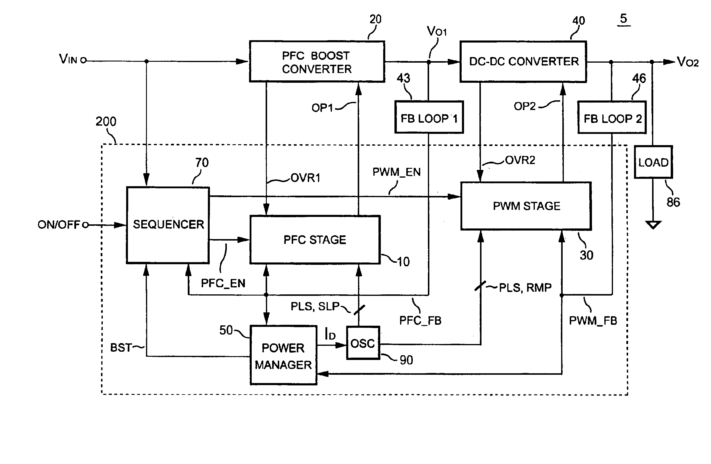
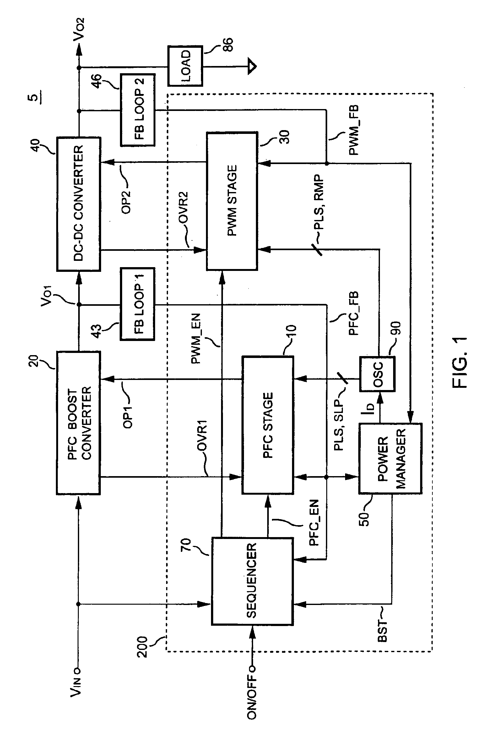
[0029]FIG. 1 shows a block diagram of a power converter 5 including a PFC-PWM controller 200 according to the present invention. The PFC-PWM controller 200 includes a PFC stage 10. The PFC stage 10 generates a PFC signal OP1 in response to a line voltage VIN and a feedback voltage PFC_FB to control the PFC boost converter 20. The feedback voltage PFC_FB is derived from a PFC boost converter feedback loop 43. When the feedback voltage PFC_FB decreases, this represents a proportional decrement of a load 86 of the power converter 5, and an increment in an output voltage VO1 of the PFC boost converter 20.

[0030]The PFC-PWM controller 200 further includes a PWM stage 30 for generating a PWM signal OP2 in response to a feedback voltage PWM_FB. The PWM signal OP2 is used to control a DC-to-DC power converter 40. The feedback voltage PWM_FB is derived from a DC-to-DC power converter feedback loop 46. When the feedback voltage PWM_FB decreases, this represents a proportional of the load 86 of...


PUM


Abstract

The present invention discloses a PFC-PWM controller having interleaved switching. A PFC stage generates a PFC signal for switching a PFC boost converter of a power converter. A PWM stage generates a PWM signal for switching a DC-to-DC converter of the power converter. The PFC-PWM controller includes a power manager for generating a discharge current and a burst-signal. Under light-load conditions, the discharge current decreases in proportion to a load of the power converter. The burst signal is utilized to disable the PFC signal in a suspended condition for power saving. A pulse width of the pulse-signal ensures a dead time to spread switching signals, such as the PFC and PWM signals, and reduces switching noise. When the discharge current decreases, the pulse width of the pulse-signal will increase and a frequency of the pulse-signal will decrease correspondingly. This further reduces power consumption under light-load and zero-load conditions.

Description

BACKGROUND OF THE INVENTION[0001]1. Field of the Invention[0002]The present invention generally relates to the field of switching mode power converters. More particularly, the present invention relates to PFC-PWM controllers.[0003]2. Description of the Prior Art[0004]The purpose of Power Factor Correction (PFC) is to correct a line current of a power supply. Power Factor Correction produces a sinusoidal input current waveform that is in phase with a line input voltage. With a PFC circuitry in a front-end of the power supply, a DC-to-DC converter can significantly reduce power loss and heat dissipation in power contribution systems.[0005]Recently enacted environmental regulations in the U.S. and in Europe not only require most consumer products to have built-in PFC function, but also strictly limit overall power consumption. Specifically, the amount of power consumption permitted for supervising and remote control purposes has been significantly reduced. Therefore, reducing power con...

Claims


Application Information

Patent Timeline
Patent Type & Authority Patents(United States)
IPC IPC(8): G05F1/40G05F1/44G05F1/10H02M3/00H02M1/00H02M1/42
CPCH02M1/4225H02M2001/0032Y02B70/16Y02B70/126H02M2001/007Y02B70/10Y02P80/10H02M1/0032H02M1/007
Inventor YANG, TA-YUNG
Owner SEMICON COMPONENTS IND LLC
Why Eureka
Try Eureka