Video amplifier for a radar receiver

a video amplifier and radar receiver technology, applied in the field of radar systems, can solve the problems of affecting the dynamic range of the receiver, affecting the design of the receiver, and the pin diode is relatively expensive, so as to reduce the effect of leakage signals, reduce aliasing, and eliminate temperature-induced gain variations

Inactive Publication Date: 2005-06-07
VALEO RADAR SYST
View PDF212 Cites 12 Cited by
  • Summary
  • Abstract
  • Description
  • Claims
  • Application Information

AI Technical Summary

Benefits of technology

[0007]According to the invention, a video amplifier is provided with a first filter stage having an input terminal adapted to receive an RF signal and an output terminal, an attenuator having an input terminal coupled to the output terminal of the first filter stage and an output terminal, and a second filter stage having an input terminal coupled to the output terminal of the attenuator and an output terminal at which an output signal of the video amplifier is provided. The attenuator includes a temperature sensitive device, such as a thermistor. This arrangement provides a relatively simple and inexpensive way to compensate for temperature induced gain variations in an RF amplifier. This is because the temperature compensation is implemented in the low video frequency amplifier and thus, can be achieved with a relatively inexpensive thermistor arranged in a simple voltage divider network. By compensating for temperature induced gain variations, the dynamic range over which the analog-to-digital converter must operate is reduced.
[0008]In one embodiment, each of the first and second filter stages has a bandpass characteristic generated by high and low pass filters. Attenuation of low frequency signals advantageously reduces leakage signals which can occur in bistatic radar systems. Further, in the illustrative FMCW radar system, low frequency attenuation is used to vary the sensitivity of the radar receiver as a function of frequency and thus, range in such a way that the amplified radar return is substantially independent of range.
[0011]In one embodiment, the radar system further includes an analog-to-digital converter responsive to the output signal of the video amplifier for providing a digital signal, a temperature sensor to provide a signal indicative of the temperature of the receiver, and a digital signal processor. The digital signal processor is responsive to the temperature indicative signal for varying a threshold used to process the digital signal. With this arrangement, a final temperature compensation can be made by the digital signal processor to eliminate any temperature induced gain variations in the RF amplifier which are not compensated by the video amplifier.
[0012]According to a further aspect of the invention, the first and second filter stages of the video amplifier have a bandpass characteristic provided by high and low pass filters. With this arrangement, the video amplifier not only reduces aliasing due to its attenuation of high frequency signals, but also reduces the effects of leakage signals due to its attenuation of low frequency signals. The low frequency attenuation further serves to vary the sensitivity of the radar receiver as a function of frequency and thus, range in such a way that the amplified radar return signal is substantially independent of range.

Problems solved by technology

Such a radar receiver suffers from several design challenges.
A further challenge in designing a radar receiver is to compensate for temperature induced gain variations in the RF amplifier, which can be significant particularly in the case of a gallium arsenide (GaAs) amplifier.
However, this approach adversely affects the dynamic range of the receiver.
However, PIN diodes are relatively expensive and add undesirable complexity to the circuit.

Method used


Image

  • Video amplifier for a radar receiver
  • Video amplifier for a radar receiver
  • Video amplifier for a radar receiver

Examples


Embodiment Construction

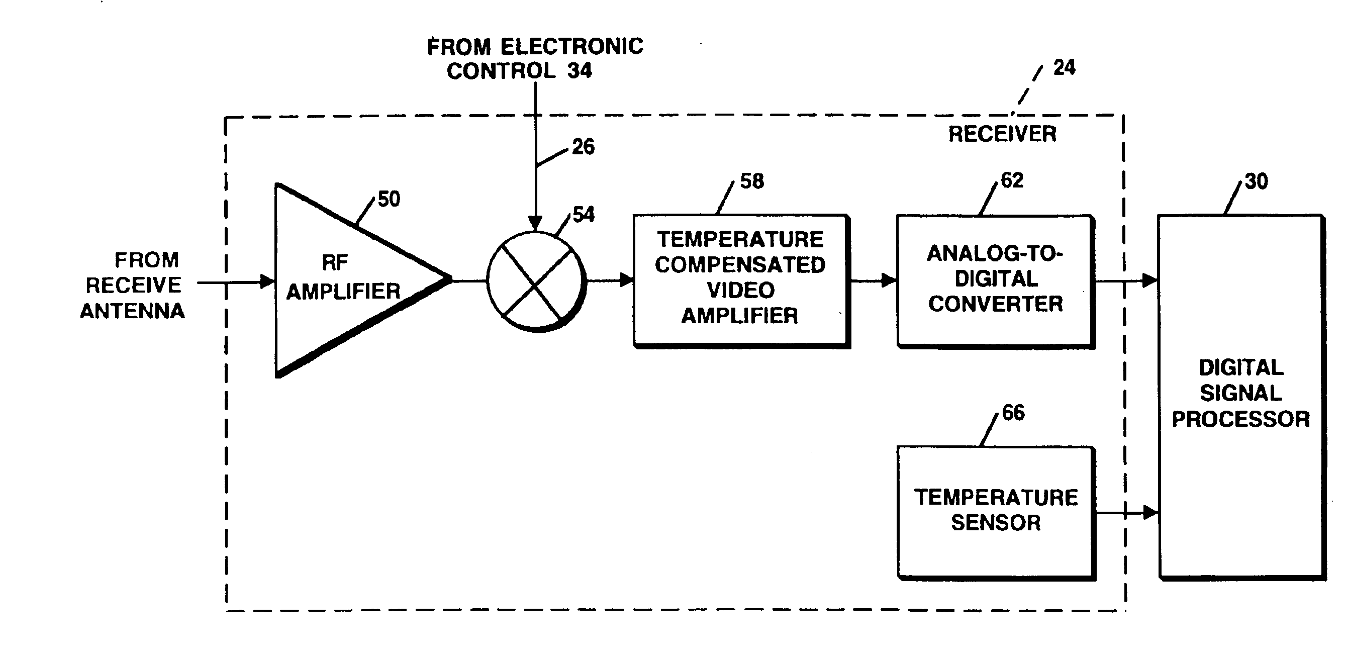
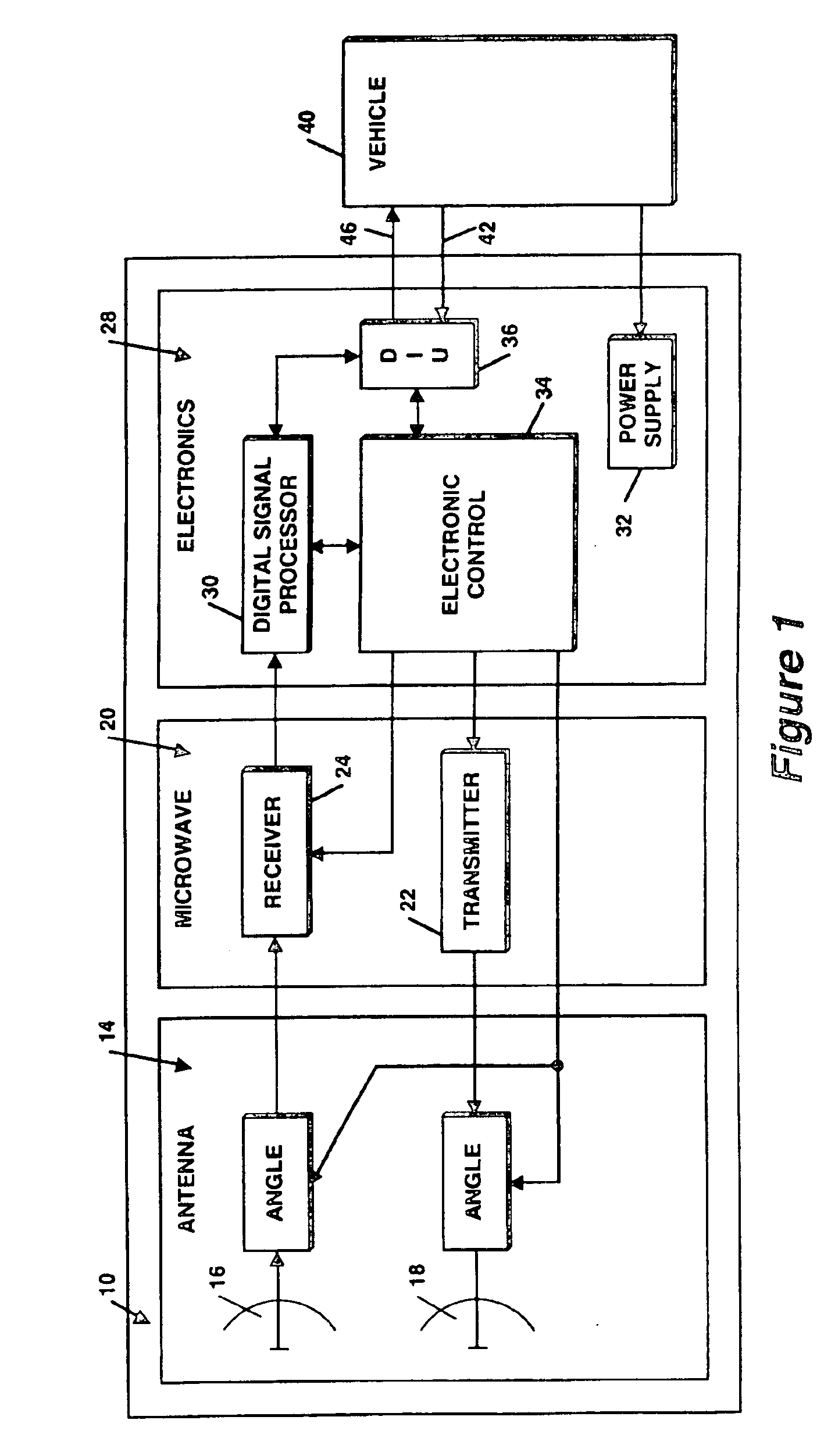
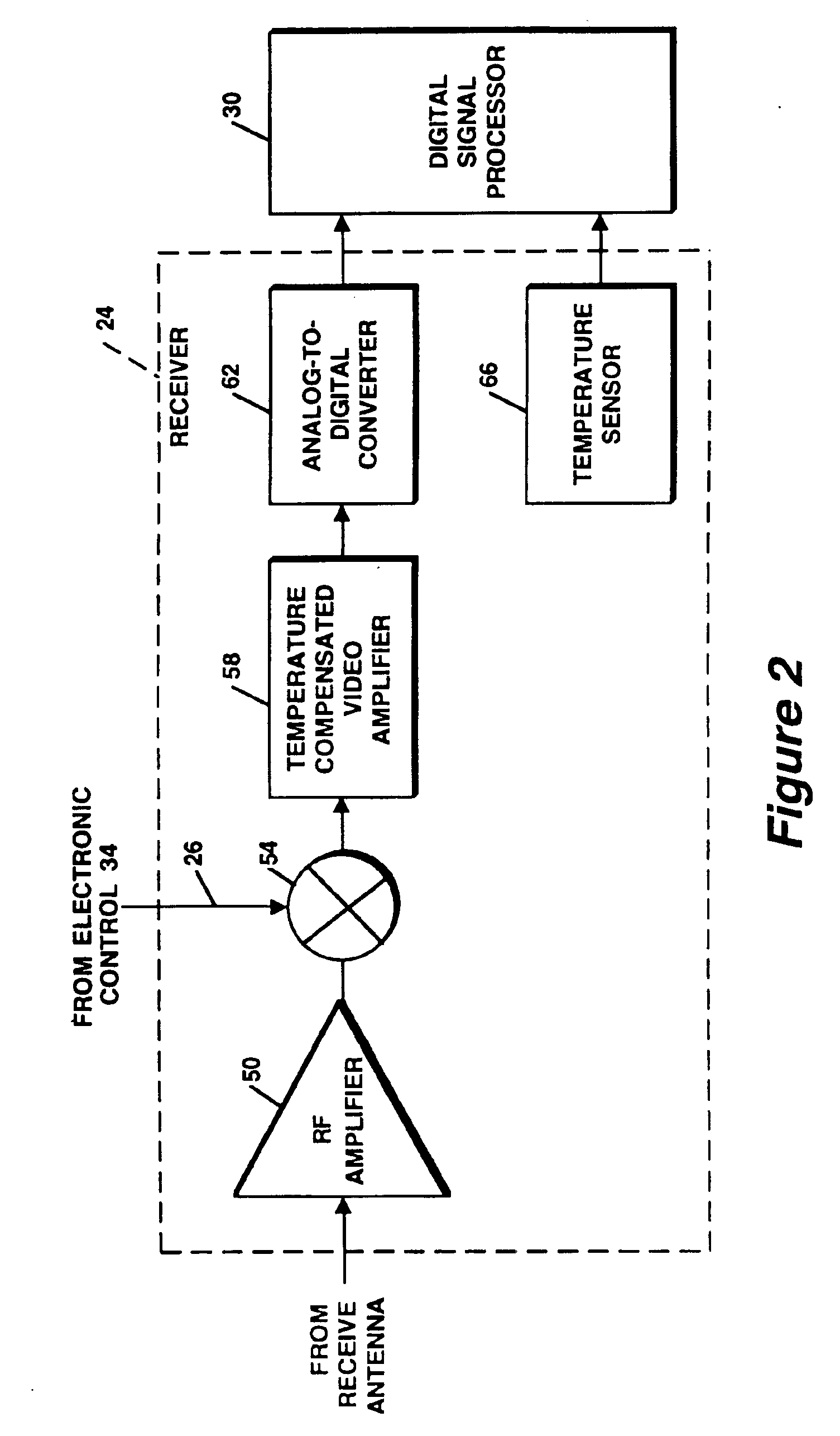
[0021]Referring to FIG. 1, a radar system 10 includes an antenna portion 14, a microwave portion 20 having both a transmitter 22 and a receiver 24, and an electronic portion 28, consisting of a digital signal processor (DSP) 30, power supplies 32, control circuits 34 and a digital interface unit 36. According to the invention, the receiver 24 includes a temperature compensated video amplifier 58 (FIG. 2).

[0022]The radar system 10 utilizes radar technology to detect one or more objects, or targets in the field of view of the system and may be used in various applications. In the illustrative example, the radar system 10 is a module of an automotive radar system (FIG. 7), such as a Side Object Detection (SOD) module or system, adapted for mounting on an automobile 40 for the purpose of detecting objects, such as other vehicles, trees, signs, pedestrians, etc. As will become apparent to those of ordinary skill in the art, the video amplifier contained in the receiver according to the p...


PUM


Abstract

A video amplifier for a radar receiver includes a temperature compensating attenuator. The attenuator includes a temperature sensitive device, such as a thermistor, arranged in a voltage divider network and is coupled in cascade between two filter stages. Each of the filter stages has a bandpass characteristic in order to filter low-frequency leakage signals and provide sensitivity control based on frequency and thus range, while also filtering high frequency signals to reduce aliasing.

Description

CROSS-REFERENCE TO RELATED APPLICATIONS[0001]This application claims the benefit of U.S. Provisional Application No. 60 / 226,160, filed on Aug. 16, 2000 and is hereby incorporated herein by reference in its entirety.STATEMENTS REGARDING FEDERALLY SPONSORED RESEARCH[0002]Not applicable.FIELD OF THE INVENTION[0003]This invention relates generally to radar systems and more particularly to a radar receiver having a video amplifier with temperature compensation.BACKGROUND OF THE INVENTION[0004]As is known in the art, radar receivers include circuitry for receiving electromagnetic radiation reflected by objects within a field of view of the radar system. Typical functions of a radar receiver include signal amplification at radio frequencies (RF), down-conversion to convert the RF frequency of the received signal to a lower, video frequency, signal filtering, and analog-to-digital conversion to provide a digital signal for further processing, such as by a Digital Signal Processor (DSP), in ...

Claims


Application Information

Patent Timeline
Patent Type & Authority Patents(United States)
IPC IPC(8): B60Q1/50B60Q1/52B60Q1/26G01S13/93G01S13/34G01S13/87G01S13/48G01S13/00G01S13/04G01S13/28G01S7/03G01S7/02G01S7/35G01S7/40G01S7/04G01S7/26H01Q13/10H01Q21/06H01Q3/24H01Q25/00H01Q21/00H01Q1/32G01S7/288G01S7/285B60R21/00B60K31/00G01S13/02G01S13/58G01S13/72G01S13/89G01S13/931H01Q1/38H01Q1/42H01Q3/26H01Q3/40H01Q13/06H03F1/30H03H7/01H03H21/00
CPCB60K31/0008G01S13/346G01S7/023G01S7/032G01S7/06G01S7/354G01S7/4004G01S7/4021G01S13/04G01S13/282G01S13/343G01S13/48G01S13/584G01S13/87G01S13/931H01Q1/3233H01Q1/3258H01Q1/3283H01Q1/38H01Q1/42H01Q3/24H01Q3/40H01Q13/10H01Q13/18H01Q21/0043H01Q21/0075H01Q21/0087H01Q21/065H01Q25/00B60Q9/008B60T2201/081B60T2201/088B60W2530/10B60W2550/304G01S7/038G01S7/288G01S7/4008G01S13/726G01S2007/356G01S2013/0245G01S2013/9321G01S2013/9332G01S2013/9375G01S2013/9378G01S2013/9385G01S2013/9389G01S7/352B60T2201/08B60W2554/803G01S2013/9315G01S2013/93271G01S2013/93272G01S2013/93274G01S2013/93275B60W2554/4043G01S7/356G01S7/0232G01S7/35
Inventor HANSON, JAMES T.WOODINGTON, WALTER GORDONDELCHECCOLO, MICHAEL JOSEPHPLEVA, JOSEPH S.RUSSELL, MARK E.VAN REES, H. BARTELD
Owner VALEO RADAR SYST
Why Eureka
Try Eureka