
Method and apparatus for performing high-speed traffic shaping

a traffic shaping and high-speed technology, applied in the field of computer networks, can solve the problems that the current software solutions for performing traffic shaping are becoming less efficient at performing their message processing tasks, and achieve the effect of high speed

Inactive Publication Date: 2005-06-07
CISCO TECH INC
View PDF19 Cites 27 Cited by
  • Summary
  • Abstract
  • Description
  • Claims
  • Application Information

AI Technical Summary

Benefits of technology

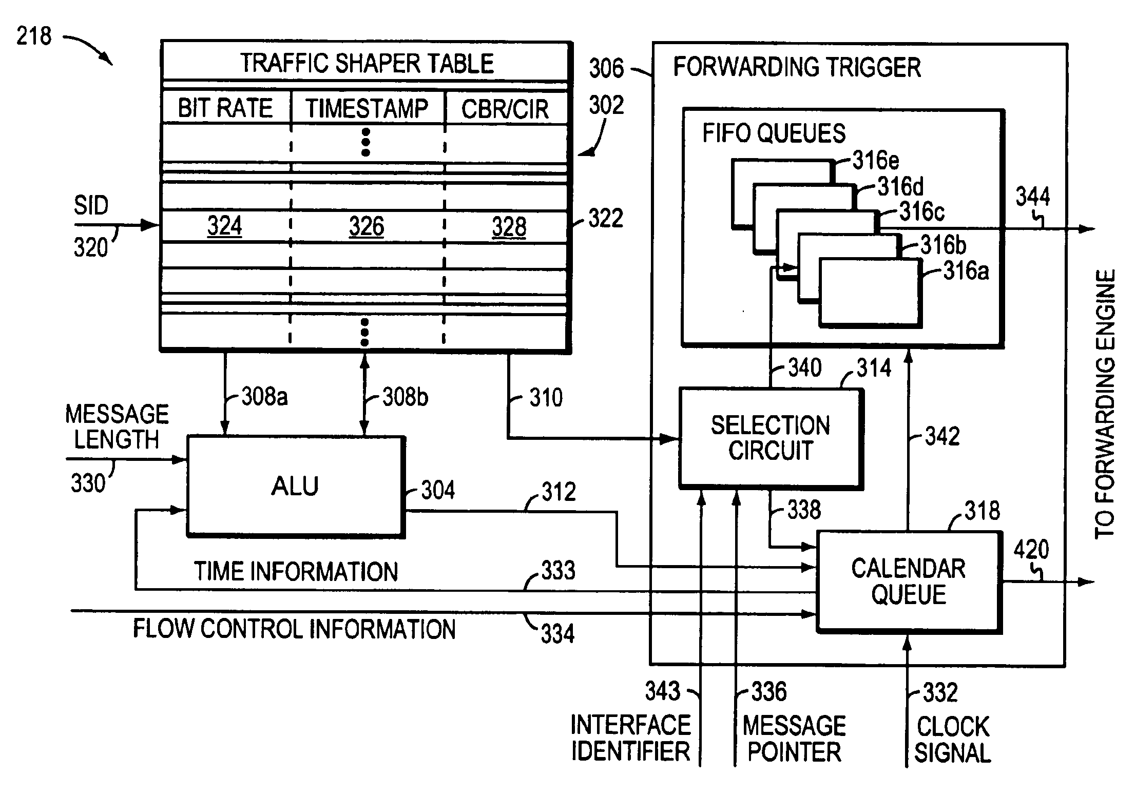
[0008]This information is then provided to the traffic shaper along with the location of the message in the respective message buffer. The traffic shaper determines a time at which transmission of the message may start in accordance with the associated traffic specifier, and stores this transmission start time together with the message's buffer location in a time-searchable queue. The forwarding trigger runs a retrieve time counter that is allowed to equal but not exceed the system time and constantly compares this retrieve time with the transmission start times associated with messages stored in the time-searchable queue. When the transmission start time of a given message matches the retrieve time, the forwarding trigger causes the given message to be fetched from the buffer and forwarded from the intermediate network device. The configuration of the traffic shaper of the present invention, including the high-speed forwarding trigger mechanism, both of which are preferably implemented through integrated hardware components, allows messages to be processed at high rates of speed, including Gigabit per second transmission rates.

Problems solved by technology

The current software solutions for performing traffic shaping are becoming less efficient at performing their message processing tasks as transmission rates reach such high speeds.

Method used


Image

  • Method and apparatus for performing high-speed traffic shaping
  • Method and apparatus for performing high-speed traffic shaping
  • Method and apparatus for performing high-speed traffic shaping

Examples


Embodiment Construction

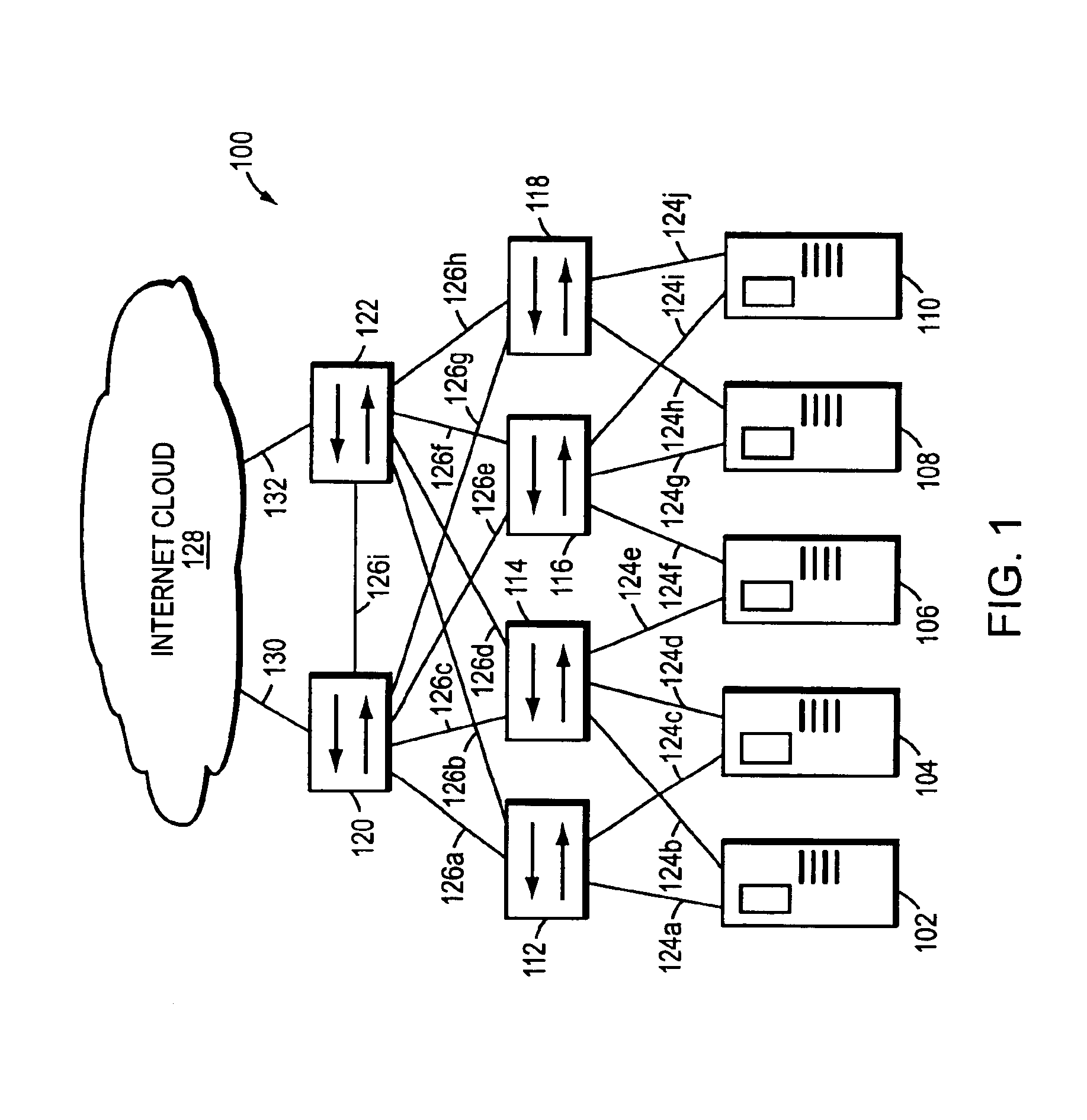
[0017]FIG. 1 is a highly schematic illustration of a computer network 100. The network 100 includes a plurality of servers 102-110 that are preferably configured as web-hosting servers. The network 100 further includes a plurality of intermediate network devices 112-122, such as backbone routers, high-speed switches, etc. Each web server 102-110 is preferably coupled to two or more of the devices 112-122 by respective trunks or links 124a-j. Server 102, for example, is coupled to device 112 by link 124a, and to device 114 by link 124b. The devices 112-122 are similarly interconnected with each other by another set of trunks or links 126a-i. Significantly, the network 100 is also coupled to the well-known Internet, which may be represented by an Internet cloud 128. In particular, device 120 is coupled to the Internet 128 by link 130, and device 122 is coupled to the Internet by link 132. Accordingly, network 100 allows users (not shown) coupled to Internet cloud 128 through other net...


PUM


Abstract

A network traffic shaper includes a traffic shaper table for storing traffic specifiers, such as permissible data transmission rates, an arithmetic logic unit (ALU), and a high-speed forwarding trigger mechanism having at least one time-searchable data structure or queue and a retrieve time generator that substantially tracks, but never exceeds, a system time. As network messages are received, they are stored at a message buffer and certain message parameters, including message length and a corresponding traffic specifier, are provided to the traffic shaper. The traffic shaper determines when the message may be sent in accordance with the associated traffic specifier and stores this transmission start time along with the message's buffer location in the time-searchable queue of the forwarding trigger. The forwarding trigger continuously examines the transmission start times for previously stored messages. When the transmission start time of a given message matches the retrieve time generator, the forwarding trigger mechanism signals that the message may be sent.

Description

FIELD OF THE INVENTION[0001]The present invention relates generally to the field of computer networks, and more specifically, to a mechanism for shaping network traffic flows at high speed.BACKGROUND OF THE INVENTION[0002]Enterprises, including businesses, governments and educational institutions, rely on computer networks to share and exchange information. A computer network typically comprises a plurality of entities interconnected by a communications media. An entity may consist of any device, such as a host or end station, that sources (i.e., transmits) and / or receives network messages over the communications media. A common type of computer network is a local area network (“LAN”) which typically refers to a privately owned network within a single building or campus. In many instances, several LANs may be interconnected by point-to-point links, microwave transceivers, satellite hookups, etc. to form a wide area network (“WAN”) or subnet that may span an entire city, country or c...

Claims


Application Information

Patent Timeline
Patent Type & Authority Patents(United States)
IPC IPC(8): H04L12/26H04L12/56
CPCH04L47/22H04L47/10
Inventor GAI, SILVANOEDSALL, THOMAS J.
Owner CISCO TECH INC
Learn More